The figure shows acircuit that illustrates the concept ofloops, which arecolored red and labeled loop...
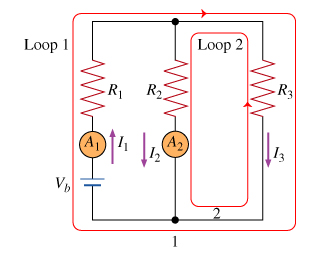
The figure shows a circuit that illustrates the concept of loops, which are colored red and labeled loop 1 and loop 2. Loop 1 is the loop around the entire circuit, whereas loop 2 is the smaller loop on the right. To apply the loop rule you would add the voltage changes of all circuit elements around the chosen loop. The figure contains two junctions (where three or more wires meet)--they are at the ends of the resistor labeled R3. The battery supplies a constant voltage Vb, and the resistors are labeled with their resistances. The ammeters are ideal meters that read I1 and I2 respectively.
The direction of each loop and the direction of each current arrow that you draw on your own circuits are arbitrary. Just assign voltage drops consistently and sum both voltage drops and currents algebraically and you will get correct equations. If the actual current is in the opposite direction from your current arrow, your answer for that current will be negative. The direction of any loop is even less important: The equation obtained from a counterclockwise loop is the same as that from a clockwise loop except for a negative sign in front of every term (i.e., an inconsequential change in overall sign of the equation because it equals zero).
Part B
Apply the junction rule to the junction labeled with the number 1 (at the bottom of the resistor of resistance R2).
Answer in terms of given
quantities, together with the meter readings I1 and I2 and the current I3 .
Part C
Apply the loop rule to loop 2 (the smaller loop on the right). Sum the voltage changes across each circuit element around this loop going in the direction of the arrow. Remember that the current meter is ideal.
Express the voltage drops in terms
of Vb, I2, I3, the given resistances, and any other given quantities.
Part D
Now apply the loop rule to loop 1 (the larger loop spanning the entire circuit). Sum the voltage changes across each circuit element around this loop going in the direction of the arrow.
Express the voltage drops in terms of Vb, I1, I3the given resistances, and any other given quantities.
Homework Answers
Part B)
Note that at junction 1, I2 and I3 are going "into" it whileI1 is "comingout". Assign a positive sign to currents flowing in and anegative to the ones flowing out. If you add all the currents you should geta zero: I2 + I3 - I1 = 0.
Part C)
Starting from point 1 and following the counter clockwise direction loop in red:
Since we are moving against I3, we get a "rise" in potential through resistor R3: I3R3
Through R2 we have a "drop" since we are moving in the same direction as I2: -I2R2
In a loop the sum of potentials differences must be zero, so: I3R3 - I2R2 = 0
Part D)
Staring from point 1 and using the same principles used in part C, but know moving clockwise
we get: Vb - I1R1 - I3R3 = 0
Add Answer to:
The figure shows acircuit that illustrates the concept ofloops, which arecolored red and labeled loop...
a) Apply the junction rule to the junction labeled with the number1 (at the bottom of...
 a) Apply the junction rule to the junction labeled with the number1
(at the bottom of the resistor of resistance ).
Answer in terms of given
quantities,together with the meter readings
and and the
current .
b) Apply the loop rule to loop 2 (the smaller loop on the
right).Sum the voltage changes across each circuit element around
thisloop going in the direction of the arrow. Remember that the
currentmeter is ideal.
Express the voltage drops in terms
of,
,...
a) Apply the junction rule to the junction labeled with the number1
(at the bottom of the resistor of resistance ).
Answer in terms of given
quantities,together with the meter readings
and and the
current .
b) Apply the loop rule to loop 2 (the smaller loop on the
right).Sum the voltage changes across each circuit element around
thisloop going in the direction of the arrow. Remember that the
currentmeter is ideal.
Express the voltage drops in terms
of,
,...
Assume the resistance values are R1 = 2,200 Ohm, R2 = 1,300 Ohm, R3 = 4,200...
 Assume the resistance values are R1 = 2,200 Ohm, R2 = 1,300 Ohm, R3 = 4,200 Ohm, and R4 = 5,900 Ohm, and the battery emfs are epsilon1 = 1.5 V and Epsilon2 = 3.0 V. Use Kirchhoff?s rules to analyze the circuit in the figure below. (a) Let I1 be the branch current though R1, I2 be the branch current through R2, and I3 be the branch current through R3. Write Kirchhoff?s loop rule relation for a loop that...
Question 1 (15 Marks): The electrical circuit shown consists of resistors and voltage sources. We can determine the current in each resistor, using the mesh current method based on Kirchhoffs voltage...
 Question 1 (15 Marks): The electrical circuit shown consists of resistors and voltage sources. We can determine the current in each resistor, using the mesh current method based on Kirchhoffs voltage law. (Kirchhoff's voltage law states that the sum of the voltage around a closed circuit is zero) 2 Σ vsource-IR = 0 i3 IH - Note: if two currents passes through one resistor we should use difference or summation between them based on direction of the currents i.e ii-j^,....
please help with problems 7 and 8, I am extremely confused! Part 2: Kirchhoff's Rules For...
 please help with problems 7 and 8, I am extremely
confused!
Part 2: Kirchhoff's Rules For the circuit shown below, the directions of the currents through the circuit elements has been chosen arbitrarily. Using Kirchhoff's rules, you will determine the actual currents through the circuit elements. (Yes, this circuit could be analyzed using equivalent resistance, but don't do it that way.) R1: 752 Kirchhoff's Junction Rule 4) Start by choosing a junction. Write Kirchhoft's Junction rule for that junction below...
please help with problems 7 and 8, I am extremely
confused!
Part 2: Kirchhoff's Rules For the circuit shown below, the directions of the currents through the circuit elements has been chosen arbitrarily. Using Kirchhoff's rules, you will determine the actual currents through the circuit elements. (Yes, this circuit could be analyzed using equivalent resistance, but don't do it that way.) R1: 752 Kirchhoff's Junction Rule 4) Start by choosing a junction. Write Kirchhoft's Junction rule for that junction below...
A circuit is constructed with six resistors and two batteries asshown. The battery voltages are...
A circuit is constructed with six resistors and two batteries as shown. The battery voltages are V1 = 18 V and V2 = 12 V. The positive terminals are indicated with a + sign, The values for the resistors are: R1 = R5 = 55 ?, R2 = R6 = 148 ? R3 = 84 ?, and R4 = 76 ?. The positive directions for the currents I1, I2 and I3 are indicated by the directions of the arrows.1)What is...
In the circuit of the figure below, the current I1 is 2.4 A and the values...
In the circuit of the figure below, the current I1 is 2.4 A and the values of e m f and R are unknown. What are the currents I2 and I3? (Enter the magnitude only.) I2 = I3 = A circuit is comprised of two adjacent square loops that share a side such that the right side of the left loop is also the left side of the right loop. The two loops meet at point a at the top...
+Vs- -V 8 LBC BLS 11 Als 12 11 E Loop (1) R2 Loop (2)R3 L2...
 +Vs- -V 8 LBC BLS 11 Als 12 11 E Loop (1) R2 Loop (2)R3 L2 GI G2 G3 Figure (6.1): Two loop circuit with two emfs 3 B A R1 R2 R3Z GI G2 G3 Figure (6.2): Series and parallel resistors + Vs - B 11 A 13 С 12 11 R1 Red R3 GI G2 G3 Figure (6.3): Series and parallel resistor circuit 4 V. ANALYSIS: Procedure (1): Two Loop Circuit 1. Verify KLR for each loop by...
What is Faraday's Law? o It defines the induced voltage across a coil when the magnetic...
 What is Faraday's Law? o It defines the induced voltage across a coil when the magnetic field going through it changes. o It gives the direction of the induced current going through a coil when the magnetic field going through it changes. O The potential difference across a resistor is proportional to both the resistance and the current going through it O The sum of all the current going into a junction has to equal the sum of all the...
Junction Rule: I1+I2=I3 (1) Loop Rule: Loop ABEFA ε1-I1R1-I3R3=0 2
 Junction Rule:
I1+I2=I3
(1)
Loop Rule: Loop ABEFA
ε1-I1R1-I3R3=0
2
Loop Rule: Loop CDEFC
ε2-I2R2-I3R3=0
(3)
HOW DO YOU FIND THE CALCULATED CURRENT PLEASE SHOW THE STEPS!
THANK YOU
Data Table 2 1 2 3 4 5 Measured Voltage Calculated Current (Using Ohm's Law) Measured Current Calculated Current (Using Equation 1-3) % error (compare column 3 and 4) R1 AVAB -5.51 0.045 0.05 R2 AVCD -3.51 0.043 0.04 RE AVEF-4.49 0.089 0.09 ** Currents in column 2 and 4 should...
Junction Rule:
I1+I2=I3
(1)
Loop Rule: Loop ABEFA
ε1-I1R1-I3R3=0
2
Loop Rule: Loop CDEFC
ε2-I2R2-I3R3=0
(3)
HOW DO YOU FIND THE CALCULATED CURRENT PLEASE SHOW THE STEPS!
THANK YOU
Data Table 2 1 2 3 4 5 Measured Voltage Calculated Current (Using Ohm's Law) Measured Current Calculated Current (Using Equation 1-3) % error (compare column 3 and 4) R1 AVAB -5.51 0.045 0.05 R2 AVCD -3.51 0.043 0.04 RE AVEF-4.49 0.089 0.09 ** Currents in column 2 and 4 should...
A circuit is constructed with six resistors and two batteries as shown The battery voltages are V1=18 V and V2=12 V.
 A circuit is constructed with six resistors and two batteries as shown The battery voltages are V1=18 V and V2=12 V. The positive terminals are indicated with a + sign, The values for the resistors are: R1=R5=66 Ω, R2=R6=83 Ω R3=55 Ω, and R4=69 Ω. The positive directions for the currents I1, I2 and I3 are indicated by the directions of the arrows.1) What is V4, the magnitude of the voltage across the resistor R4? 2) What is I3, the current...
 a) Apply the junction rule to the junction labeled with the number1
(at the bottom of the resistor of resistance ).
Answer in terms of given
quantities,together with the meter readings
and and the
current .
b) Apply the loop rule to loop 2 (the smaller loop on the
right).Sum the voltage changes across each circuit element around
thisloop going in the direction of the arrow. Remember that the
currentmeter is ideal.
Express the voltage drops in terms
of,
,...
a) Apply the junction rule to the junction labeled with the number1
(at the bottom of the resistor of resistance ).
Answer in terms of given
quantities,together with the meter readings
and and the
current .
b) Apply the loop rule to loop 2 (the smaller loop on the
right).Sum the voltage changes across each circuit element around
thisloop going in the direction of the arrow. Remember that the
currentmeter is ideal.
Express the voltage drops in terms
of,
,...
 Assume the resistance values are R1 = 2,200 Ohm, R2 = 1,300 Ohm, R3 = 4,200 Ohm, and R4 = 5,900 Ohm, and the battery emfs are epsilon1 = 1.5 V and Epsilon2 = 3.0 V. Use Kirchhoff?s rules to analyze the circuit in the figure below. (a) Let I1 be the branch current though R1, I2 be the branch current through R2, and I3 be the branch current through R3. Write Kirchhoff?s loop rule relation for a loop that...
 Question 1 (15 Marks): The electrical circuit shown consists of resistors and voltage sources. We can determine the current in each resistor, using the mesh current method based on Kirchhoffs voltage law. (Kirchhoff's voltage law states that the sum of the voltage around a closed circuit is zero) 2 Σ vsource-IR = 0 i3 IH - Note: if two currents passes through one resistor we should use difference or summation between them based on direction of the currents i.e ii-j^,....
 please help with problems 7 and 8, I am extremely
confused!
Part 2: Kirchhoff's Rules For the circuit shown below, the directions of the currents through the circuit elements has been chosen arbitrarily. Using Kirchhoff's rules, you will determine the actual currents through the circuit elements. (Yes, this circuit could be analyzed using equivalent resistance, but don't do it that way.) R1: 752 Kirchhoff's Junction Rule 4) Start by choosing a junction. Write Kirchhoft's Junction rule for that junction below...
please help with problems 7 and 8, I am extremely
confused!
Part 2: Kirchhoff's Rules For the circuit shown below, the directions of the currents through the circuit elements has been chosen arbitrarily. Using Kirchhoff's rules, you will determine the actual currents through the circuit elements. (Yes, this circuit could be analyzed using equivalent resistance, but don't do it that way.) R1: 752 Kirchhoff's Junction Rule 4) Start by choosing a junction. Write Kirchhoft's Junction rule for that junction below...
 +Vs- -V 8 LBC BLS 11 Als 12 11 E Loop (1) R2 Loop (2)R3 L2 GI G2 G3 Figure (6.1): Two loop circuit with two emfs 3 B A R1 R2 R3Z GI G2 G3 Figure (6.2): Series and parallel resistors + Vs - B 11 A 13 С 12 11 R1 Red R3 GI G2 G3 Figure (6.3): Series and parallel resistor circuit 4 V. ANALYSIS: Procedure (1): Two Loop Circuit 1. Verify KLR for each loop by...
 What is Faraday's Law? o It defines the induced voltage across a coil when the magnetic field going through it changes. o It gives the direction of the induced current going through a coil when the magnetic field going through it changes. O The potential difference across a resistor is proportional to both the resistance and the current going through it O The sum of all the current going into a junction has to equal the sum of all the...
 Junction Rule:
I1+I2=I3
(1)
Loop Rule: Loop ABEFA
ε1-I1R1-I3R3=0
2
Loop Rule: Loop CDEFC
ε2-I2R2-I3R3=0
(3)
HOW DO YOU FIND THE CALCULATED CURRENT PLEASE SHOW THE STEPS!
THANK YOU
Data Table 2 1 2 3 4 5 Measured Voltage Calculated Current (Using Ohm's Law) Measured Current Calculated Current (Using Equation 1-3) % error (compare column 3 and 4) R1 AVAB -5.51 0.045 0.05 R2 AVCD -3.51 0.043 0.04 RE AVEF-4.49 0.089 0.09 ** Currents in column 2 and 4 should...
Junction Rule:
I1+I2=I3
(1)
Loop Rule: Loop ABEFA
ε1-I1R1-I3R3=0
2
Loop Rule: Loop CDEFC
ε2-I2R2-I3R3=0
(3)
HOW DO YOU FIND THE CALCULATED CURRENT PLEASE SHOW THE STEPS!
THANK YOU
Data Table 2 1 2 3 4 5 Measured Voltage Calculated Current (Using Ohm's Law) Measured Current Calculated Current (Using Equation 1-3) % error (compare column 3 and 4) R1 AVAB -5.51 0.045 0.05 R2 AVCD -3.51 0.043 0.04 RE AVEF-4.49 0.089 0.09 ** Currents in column 2 and 4 should...
Most questions answered within 3 hours.
-
Suppose that XX is a random variable with mean 16 and standard
deviation 5 . Also...
asked 22 minutes ago -
Calculate the number density of argon gas at a temperature of
24C and a pressure of...
asked 3 hours ago -
Alternative
Classification
How to Estimate
Probabilities from Data? ( For continuous Attributes)
And How to generate...
asked 3 hours ago -
An explosion breaks a 20.0-kg object into three parts. The
object is initially moving at a...
asked 4 hours ago -
Calculate the approximate number of residues of Rubisco, which
is involved in carbon fixation in plants,...
asked 5 hours ago -
Other decisions about scientific claims can have a much broader
impact.ENERGYarrow-10x10.png, environment, health, security - all...
asked 6 hours ago -
I need to write a research paper and work cited about this
topic: The United States...
asked 6 hours ago -
Hello! I was wondering if I could have some help?
If the vapor pressure of carvone...
asked 7 hours ago -
An economist wants to estimate the mean per capita income (in
thousands of dollars) for a...
asked 7 hours ago -
What would be the input/output characteristic of a circuit
obtained by putting two of your 2's-complementers...
asked 7 hours ago -
In Drosophila, the transition from the syncytial blastoderm
stage to the cellular blastoderm stage is a...
asked 7 hours ago -
Project management question:
Name 3 different types of resources (hint: humans are one
type)
asked 8 hours ago