
Homework Answers
Add Answer to:
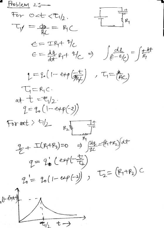
Problem 2: /10 A) For the RC circuit of Figure 1, the switch is put in...
Problem 1: /10 A) For the RL circuit of Figure 1, the switch is closed at...
 Problem 1: /10 A) For the RL circuit of Figure 1, the switch is closed at t=0 (charging phase). Report the time constant of the circuit T1 , voltage V, and current i, at time t = t1/2 23 82H £292 3v 20 20 Fig. 1: EMILM B) At time t = t;/2 , the switch in the RL circuit of Figure 1 is opened (discharging phase); Report the time constant of the circuit ta , voltage V, and current...
2 First-Order RC Circuit: Natural Response The switch in the circuit in Figure 2 has been...
 2 First-Order RC Circuit: Natural Response The switch in the circuit in Figure 2 has been in position for a long time. At t = 0, the switch moves to position (the switch opens) and stays there. Assuming that V. > O for the constant voltage source, (a) find vc(0-), vc(0+), ic(0-), and ic(0+); (b) find vc(t) when t 20 (if you want, you can write vo(t) by circuit inspection; you don't need to show the differential equation); and (c)...
Consider the RC circuit in the figure below. The switch was at position a for a long period of time and it is suddenly...
 Consider the RC circuit in the figure below. The switch was at
position a for a long period of time and it is
suddenly switched to position b at time t =
0.For
each statement select True or False.1. The current through the resistor equals the current across the
capacitor at all times.2. In the instant after the switch is thrown the current across the
capacitor is zero.3. In the instant after the switch is thrown the voltage across the...
Consider the RC circuit in the figure below. The switch was at
position a for a long period of time and it is
suddenly switched to position b at time t =
0.For
each statement select True or False.1. The current through the resistor equals the current across the
capacitor at all times.2. In the instant after the switch is thrown the current across the
capacitor is zero.3. In the instant after the switch is thrown the voltage across the...
5. [RC Circuits] Consider the circuit shown in Figure 5 attached. As shown, the switch is...
 5. [RC Circuits] Consider the circuit shown in Figure 5 attached. As shown, the switch is in position "A" for t < 0, and the circuit has been at rest for a long time. At time t = 0, the switch opens and the capacitor starts to drain across the resistor. (a) When the switch is closed and there is only a direct current (DC) source, the capacitor acts like an open circuit. Find the constant voltage across the capacitor...
Questions and answers are here, need solution process. 3. a) For the circuit shown in Figure...
 Questions and answers are here, need solution process.
3. a) For the circuit shown in Figure Q3 (a): i) Find the mathematical expression for the transient behaviour of the voltage 6 vc across the capacitor and the current ic when the switch is moved into position 1 at t- 0 s ii) Find the mathematical expression for the response of vc and ic if the switch 4 is moved into position 2 at t charging phase) τ (where τ is...
Questions and answers are here, need solution process.
3. a) For the circuit shown in Figure Q3 (a): i) Find the mathematical expression for the transient behaviour of the voltage 6 vc across the capacitor and the current ic when the switch is moved into position 1 at t- 0 s ii) Find the mathematical expression for the response of vc and ic if the switch 4 is moved into position 2 at t charging phase) τ (where τ is...
(1) Consider the RC circuit shown in Figure 1. For t<0 the switch is open, and...
 (1) Consider the RC circuit shown in Figure 1. For t<0 the switch is open, and the charge stored on the capacitor is 0. At t-0 the switch is closed, and the voltage source begins charging the capacitor. Let R1-R2-220 Ω , C-0.47 μ F , Vs-5 V. (a) Write the differential equation as an expression for the capacitor voltage fort> 0 (i.e. write the differential equation) and calculate the time constant (b) Calculate the steady-state capacitor voltage R2 R1...
The switch in the circuit shown in Fig. Shown has been in position a for a...
 The switch in the circuit shown in Fig. Shown has been in position a for a long time. At t-o the switch is moved to position b. a) What is the initial value of vc? b) What is the final value of vc? c) What is the time constant of the circuit when the switch is in position a? d) What is the expression for vc(t) when t > 0? 80 V 315 kn 100 V 2F What is the...
In the circuit shown in Figure-2, the switch was in position-a for a long time. At...
 In the circuit shown in Figure-2, the switch was in position-a for a long time. At time t-0, the switch is moved to position-b. ) Att-0, calculate Vc(+). Q2: 151 1101 Solve Ve () at t20 Find Vc at t 2 sec. switch 25 Figure-2
Problem 2:(20 points) Consider the RC circuit in Figure 2. You may assume that the switch...
 Problem 2:(20 points) Consider the RC circuit in Figure 2. You may assume that the switch has been opened long enough for the voltages and currents to reach steady-state values. At time t = 0 the switch is closed. t-0 Figure 2: The switch in the RC circuit is closed at timet0 1. (6 points) Find the voltage v(0-) and the current i(0) just before the switch is closed. 2. (6 points) Find the voltage v(0+) and the current i(0+)immediately...
In the circuit shown in (Figure 1), the switch S has been closed for a long time.
 a. What is the output voltage Vout? Now the switch is opened and the output voltage increases. When the output voltage reaches 10.0 V, the switch closes and then the capacitor begins to discharge. When the output voltage reaches 5.0 V, the switch opens again. Thus this circuit undergoes periodic cycles of charging and discharging.b. What is the time constant during a charging phase?c. What is the time constant during a discharging phase?d. What length of time passes between subsequent 10.0 V output voltages?e. If...
 Problem 1: /10 A) For the RL circuit of Figure 1, the switch is closed at t=0 (charging phase). Report the time constant of the circuit T1 , voltage V, and current i, at time t = t1/2 23 82H £292 3v 20 20 Fig. 1: EMILM B) At time t = t;/2 , the switch in the RL circuit of Figure 1 is opened (discharging phase); Report the time constant of the circuit ta , voltage V, and current...
 2 First-Order RC Circuit: Natural Response The switch in the circuit in Figure 2 has been in position for a long time. At t = 0, the switch moves to position (the switch opens) and stays there. Assuming that V. > O for the constant voltage source, (a) find vc(0-), vc(0+), ic(0-), and ic(0+); (b) find vc(t) when t 20 (if you want, you can write vo(t) by circuit inspection; you don't need to show the differential equation); and (c)...
 Consider the RC circuit in the figure below. The switch was at
position a for a long period of time and it is
suddenly switched to position b at time t =
0.For
each statement select True or False.1. The current through the resistor equals the current across the
capacitor at all times.2. In the instant after the switch is thrown the current across the
capacitor is zero.3. In the instant after the switch is thrown the voltage across the...
Consider the RC circuit in the figure below. The switch was at
position a for a long period of time and it is
suddenly switched to position b at time t =
0.For
each statement select True or False.1. The current through the resistor equals the current across the
capacitor at all times.2. In the instant after the switch is thrown the current across the
capacitor is zero.3. In the instant after the switch is thrown the voltage across the...
 5. [RC Circuits] Consider the circuit shown in Figure 5 attached. As shown, the switch is in position "A" for t < 0, and the circuit has been at rest for a long time. At time t = 0, the switch opens and the capacitor starts to drain across the resistor. (a) When the switch is closed and there is only a direct current (DC) source, the capacitor acts like an open circuit. Find the constant voltage across the capacitor...
 Questions and answers are here, need solution process.
3. a) For the circuit shown in Figure Q3 (a): i) Find the mathematical expression for the transient behaviour of the voltage 6 vc across the capacitor and the current ic when the switch is moved into position 1 at t- 0 s ii) Find the mathematical expression for the response of vc and ic if the switch 4 is moved into position 2 at t charging phase) τ (where τ is...
Questions and answers are here, need solution process.
3. a) For the circuit shown in Figure Q3 (a): i) Find the mathematical expression for the transient behaviour of the voltage 6 vc across the capacitor and the current ic when the switch is moved into position 1 at t- 0 s ii) Find the mathematical expression for the response of vc and ic if the switch 4 is moved into position 2 at t charging phase) τ (where τ is...
 (1) Consider the RC circuit shown in Figure 1. For t<0 the switch is open, and the charge stored on the capacitor is 0. At t-0 the switch is closed, and the voltage source begins charging the capacitor. Let R1-R2-220 Ω , C-0.47 μ F , Vs-5 V. (a) Write the differential equation as an expression for the capacitor voltage fort> 0 (i.e. write the differential equation) and calculate the time constant (b) Calculate the steady-state capacitor voltage R2 R1...
 The switch in the circuit shown in Fig. Shown has been in position a for a long time. At t-o the switch is moved to position b. a) What is the initial value of vc? b) What is the final value of vc? c) What is the time constant of the circuit when the switch is in position a? d) What is the expression for vc(t) when t > 0? 80 V 315 kn 100 V 2F What is the...
 In the circuit shown in Figure-2, the switch was in position-a for a long time. At time t-0, the switch is moved to position-b. ) Att-0, calculate Vc(+). Q2: 151 1101 Solve Ve () at t20 Find Vc at t 2 sec. switch 25 Figure-2
 Problem 2:(20 points) Consider the RC circuit in Figure 2. You may assume that the switch has been opened long enough for the voltages and currents to reach steady-state values. At time t = 0 the switch is closed. t-0 Figure 2: The switch in the RC circuit is closed at timet0 1. (6 points) Find the voltage v(0-) and the current i(0) just before the switch is closed. 2. (6 points) Find the voltage v(0+) and the current i(0+)immediately...
Most questions answered within 3 hours.
-
what is the current research being done on the hexokinase
enzyme?
asked 1 second from now -
Let’s assume you want to retire with $1,000,000 in your
investment portfolio. Given that your investment...
asked 33 seconds ago -
profit motivation is one of the biggest differences between
public and private organizations. what about resource...
asked 25 seconds from now -
Test the hypothesis using P-value approach. Be sure to verify
the requirements of the test.
H0:...
asked 2 minutes ago -
Balance the following oxidation-reduction equations using redox
methods:
Cu + H+ --------> Cu+ +
H2
asked 3 minutes ago -
Baltimore Manufacturing had a Work in Process balance of $84,000
on January 1, 2018. The year...
asked 7 minutes ago -
Need help converting into sql language.
How many players from each town served on the committee...
asked 19 minutes ago -
A professor needs to assign 15 teaching assistants to the course
STATISTICS 101. There are 40...
asked 21 minutes ago -
A palindrome is a word, phrase, number, or other sequence of
characters which reads the same...
asked 13 minutes ago -
1. Find a grammar for L(G) = {All bit strings with twice as many
1s as...
asked 19 minutes ago -
The voltage from an AC source varies as v = 240 sin (503t)
volts. Find (a)...
asked 30 minutes ago -
In Ligedia, a country in East Asia, factory workers are exposed
to dangerous work conditions. Although...
asked 25 minutes ago