
Homework Answers
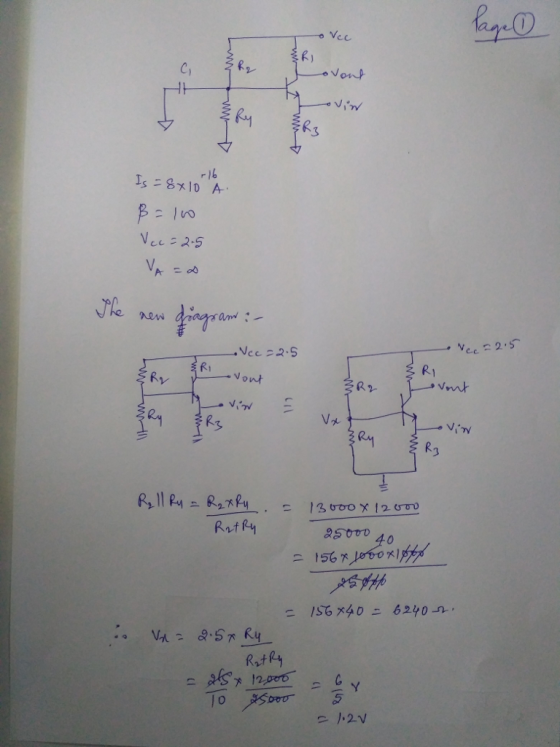

Therefore Ic= 1.0515mA
And VCE=1.4748V
This is the operating point of CB stage.
Add Answer to:
Vcc R1 R2 Vout C1 1 point 01 NPN R4 Vin R3 Determine the operating point...
R1 = 1kΩ R2 = 3kΩ R3 = R4 = 1kΩ Voffset = 1V Vin =...
 R1 = 1kΩ
R2 = 3kΩ
R3 = R4 = 1kΩ
Voffset = 1V
Vin = 2V
Determine the value of the voltage in Vout.
R1 R2 ww o Vout Vin o +15V opamp U1 15V R4 R3 Voffset
R1 = 1kΩ
R2 = 3kΩ
R3 = R4 = 1kΩ
Voffset = 1V
Vin = 2V
Determine the value of the voltage in Vout.
R1 R2 ww o Vout Vin o +15V opamp U1 15V R4 R3 Voffset
Calculate the equivalent resistance. Vin R1: 30 R2: 100: R3 60 R4 80 R5 40 Vout
 Calculate the equivalent resistance.
Vin R1: 30 R2: 100: R3 60 R4 80 R5 40 Vout
Calculate the equivalent resistance.
Vin R1: 30 R2: 100: R3 60 R4 80 R5 40 Vout
Given the circuit below: R3 C1 Vout C2 R1 R3 Vin R2 ts 1 a) derive the transfer function between ...
 Given the circuit below: R3 C1 Vout C2 R1 R3 Vin R2 ts 1 a) derive the transfer function between the input and the output in terms of R1,C1,R2,C2 b) For this and all other parts below, assume Izl<Ipl, i..e that D(s) is a lead-type compensator. The transfer function is written in the following format ts 1 Express quantities K, z, p using R1,C1,R2,C2 Also, express Κα, α, τ using K,z, p c) Observe the values of s-jw on the...
Part 1: Gain =8, R1=5k, R2=20k, R5=100, and V1=1V. Find Vout/Vin. Part 2: Let R4=0 and...
 Part 1: Gain =8, R1=5k, R2=20k, R5=100, and V1=1V. Find
Vout/Vin.
Part 2: Let R4=0 and R3=∞. Find Vout/Vin. (Hint: make sure the
button called Enable Biased Voltage
Display is depressed) (Another Hint: when a resistance is zero,
short it; when a resistance is
infinity, delete it).
Part 3: Let R4=2k and R3=∞. Find Vout/Vin.
Part 4: Let R4=0 and R3=1000. Find Vout/Vin.
Part 5:Let R4=2k and R3=1000. Find Vout/Vin.
R1 Vout G1 5k R4 1k R5 100 V1 R2...
Part 1: Gain =8, R1=5k, R2=20k, R5=100, and V1=1V. Find
Vout/Vin.
Part 2: Let R4=0 and R3=∞. Find Vout/Vin. (Hint: make sure the
button called Enable Biased Voltage
Display is depressed) (Another Hint: when a resistance is zero,
short it; when a resistance is
infinity, delete it).
Part 3: Let R4=2k and R3=∞. Find Vout/Vin.
Part 4: Let R4=0 and R3=1000. Find Vout/Vin.
Part 5:Let R4=2k and R3=1000. Find Vout/Vin.
R1 Vout G1 5k R4 1k R5 100 V1 R2...
2. For the common-emitter amplifier. B= 50. Vcc=12 a) Draw small signal circuit b) Find vout/vin...
 2. For the common-emitter amplifier. B= 50. Vcc=12 a) Draw small signal circuit b) Find vout/vin Find Zin and Zou Vcc R1 27k R2 2.2k Zout Zin Vo 4 C1 16 BIG Q1 NPN V1 C2 V R3 15k RE 1.2k BIG
Having trouble finding R1,R2,R3,R4,R5,R6 any info would be awesome
 Having trouble finding R1,R2,R3,R4,R5,R6
any info would be awesome
BJT Phase Shift Oscillator 12V VCC R3 R4 RC R1 Q2 C5 C8 R5 2N2222A C7 0.01HF 0.01HF 0.01 μF Q1 R7 C2 SineWave 2N2222A 22Ω Q-point R6 RE C4 100μF R2 lc 2ma Vce -5volts 12V VCC U1 JI LM7812CT LINE VOLTAGE VREG C3 470uF Title: FinalProject_Osc C1 0.1HF FinalProject_Osc Designed by. Dennis Leak Checked by Approved by. Document N 0001 Date: 2014-04-06 Sheet 1 Revision: 1.0 Size: A 1of...
Having trouble finding R1,R2,R3,R4,R5,R6
any info would be awesome
BJT Phase Shift Oscillator 12V VCC R3 R4 RC R1 Q2 C5 C8 R5 2N2222A C7 0.01HF 0.01HF 0.01 μF Q1 R7 C2 SineWave 2N2222A 22Ω Q-point R6 RE C4 100μF R2 lc 2ma Vce -5volts 12V VCC U1 JI LM7812CT LINE VOLTAGE VREG C3 470uF Title: FinalProject_Osc C1 0.1HF FinalProject_Osc Designed by. Dennis Leak Checked by Approved by. Document N 0001 Date: 2014-04-06 Sheet 1 Revision: 1.0 Size: A 1of...
For the electrical circuit below, let R1=30 Ohms, R2=15 Ohms, R3=10 Ohms, R4=20 Ohms, C=0.1 F...
 For the electrical circuit below, let R1=30 Ohms, R2=15 Ohms,
R3=10 Ohms, R4=20 Ohms, C=0.1 F and Vin=10V and complete the
following.
For the electrical circuit below, let R1 = 30 12, R2 = 152, R3 = 102, R1 = 20 2, C =0.1 F and Vin = 10V and complete the following. a) Use circuit analysis to derive the differential equation for the capacitor voltage, V.(t). b) Find the solution for V«(t) and sketch it for t=0, t and...
For the electrical circuit below, let R1=30 Ohms, R2=15 Ohms,
R3=10 Ohms, R4=20 Ohms, C=0.1 F and Vin=10V and complete the
following.
For the electrical circuit below, let R1 = 30 12, R2 = 152, R3 = 102, R1 = 20 2, C =0.1 F and Vin = 10V and complete the following. a) Use circuit analysis to derive the differential equation for the capacitor voltage, V.(t). b) Find the solution for V«(t) and sketch it for t=0, t and...
For the circuit shown below: In terms of Vo, R1, R2, R3, R4, C1, t, and s what is the time domain...
 For the circuit shown below: In terms of Vo, R1, R2, R3, R4, C1, t, and s what is the time domain equation for the voltage at node out? Preview In terms of Vo, R1, R2, ,R3, R4, C1, t, and s what is the s-domain equation for voltage at node out? In terms of Vo, RI, R2, R3, R4, CI, t, and s what is the equation for τ? If the voltage V1 at time-0 is 1 V R1-1...
3-F) b. Vout = 0.99 Vin 3-E) For the following circuit, with Ri 18 k2, R2...
 3-F) b. Vout = 0.99 Vin
3-E) For the following circuit, with Ri 18 k2, R2 15 k(2, R6 = 40 kQ, V,-10 V, and V,-7 V, find: 22 k2, R 30 k2, R4 20 kQ, Rs- a) the current through Ri, R3, & R6 b) the voltage across R2, R4, & Rs Rs V, 3-F) For the following circuit, what is Vout in terms of Vin for each case? a) R1-100 ?, R2-1 k(2, and R3 = 1.0 M(2...
3-F) b. Vout = 0.99 Vin
3-E) For the following circuit, with Ri 18 k2, R2 15 k(2, R6 = 40 kQ, V,-10 V, and V,-7 V, find: 22 k2, R 30 k2, R4 20 kQ, Rs- a) the current through Ri, R3, & R6 b) the voltage across R2, R4, & Rs Rs V, 3-F) For the following circuit, what is Vout in terms of Vin for each case? a) R1-100 ?, R2-1 k(2, and R3 = 1.0 M(2...
Derive an expression for Vout R3 1. Vint R1 U1 Vin2 R2 Vout + AMP SIMP...
 Derive an expression for Vout
R3 1. Vint R1 U1 Vin2 R2 Vout + AMP SIMP C 2. HE U2 Vin R + AMP SIMP
Derive an expression for Vout
R3 1. Vint R1 U1 Vin2 R2 Vout + AMP SIMP C 2. HE U2 Vin R + AMP SIMP
 R1 = 1kΩ
R2 = 3kΩ
R3 = R4 = 1kΩ
Voffset = 1V
Vin = 2V
Determine the value of the voltage in Vout.
R1 R2 ww o Vout Vin o +15V opamp U1 15V R4 R3 Voffset
R1 = 1kΩ
R2 = 3kΩ
R3 = R4 = 1kΩ
Voffset = 1V
Vin = 2V
Determine the value of the voltage in Vout.
R1 R2 ww o Vout Vin o +15V opamp U1 15V R4 R3 Voffset
 Calculate the equivalent resistance.
Vin R1: 30 R2: 100: R3 60 R4 80 R5 40 Vout
Calculate the equivalent resistance.
Vin R1: 30 R2: 100: R3 60 R4 80 R5 40 Vout
 Given the circuit below: R3 C1 Vout C2 R1 R3 Vin R2 ts 1 a) derive the transfer function between the input and the output in terms of R1,C1,R2,C2 b) For this and all other parts below, assume Izl<Ipl, i..e that D(s) is a lead-type compensator. The transfer function is written in the following format ts 1 Express quantities K, z, p using R1,C1,R2,C2 Also, express Κα, α, τ using K,z, p c) Observe the values of s-jw on the...
 Part 1: Gain =8, R1=5k, R2=20k, R5=100, and V1=1V. Find
Vout/Vin.
Part 2: Let R4=0 and R3=∞. Find Vout/Vin. (Hint: make sure the
button called Enable Biased Voltage
Display is depressed) (Another Hint: when a resistance is zero,
short it; when a resistance is
infinity, delete it).
Part 3: Let R4=2k and R3=∞. Find Vout/Vin.
Part 4: Let R4=0 and R3=1000. Find Vout/Vin.
Part 5:Let R4=2k and R3=1000. Find Vout/Vin.
R1 Vout G1 5k R4 1k R5 100 V1 R2...
Part 1: Gain =8, R1=5k, R2=20k, R5=100, and V1=1V. Find
Vout/Vin.
Part 2: Let R4=0 and R3=∞. Find Vout/Vin. (Hint: make sure the
button called Enable Biased Voltage
Display is depressed) (Another Hint: when a resistance is zero,
short it; when a resistance is
infinity, delete it).
Part 3: Let R4=2k and R3=∞. Find Vout/Vin.
Part 4: Let R4=0 and R3=1000. Find Vout/Vin.
Part 5:Let R4=2k and R3=1000. Find Vout/Vin.
R1 Vout G1 5k R4 1k R5 100 V1 R2...
 2. For the common-emitter amplifier. B= 50. Vcc=12 a) Draw small signal circuit b) Find vout/vin Find Zin and Zou Vcc R1 27k R2 2.2k Zout Zin Vo 4 C1 16 BIG Q1 NPN V1 C2 V R3 15k RE 1.2k BIG
 Having trouble finding R1,R2,R3,R4,R5,R6
any info would be awesome
BJT Phase Shift Oscillator 12V VCC R3 R4 RC R1 Q2 C5 C8 R5 2N2222A C7 0.01HF 0.01HF 0.01 μF Q1 R7 C2 SineWave 2N2222A 22Ω Q-point R6 RE C4 100μF R2 lc 2ma Vce -5volts 12V VCC U1 JI LM7812CT LINE VOLTAGE VREG C3 470uF Title: FinalProject_Osc C1 0.1HF FinalProject_Osc Designed by. Dennis Leak Checked by Approved by. Document N 0001 Date: 2014-04-06 Sheet 1 Revision: 1.0 Size: A 1of...
Having trouble finding R1,R2,R3,R4,R5,R6
any info would be awesome
BJT Phase Shift Oscillator 12V VCC R3 R4 RC R1 Q2 C5 C8 R5 2N2222A C7 0.01HF 0.01HF 0.01 μF Q1 R7 C2 SineWave 2N2222A 22Ω Q-point R6 RE C4 100μF R2 lc 2ma Vce -5volts 12V VCC U1 JI LM7812CT LINE VOLTAGE VREG C3 470uF Title: FinalProject_Osc C1 0.1HF FinalProject_Osc Designed by. Dennis Leak Checked by Approved by. Document N 0001 Date: 2014-04-06 Sheet 1 Revision: 1.0 Size: A 1of...
 For the electrical circuit below, let R1=30 Ohms, R2=15 Ohms,
R3=10 Ohms, R4=20 Ohms, C=0.1 F and Vin=10V and complete the
following.
For the electrical circuit below, let R1 = 30 12, R2 = 152, R3 = 102, R1 = 20 2, C =0.1 F and Vin = 10V and complete the following. a) Use circuit analysis to derive the differential equation for the capacitor voltage, V.(t). b) Find the solution for V«(t) and sketch it for t=0, t and...
For the electrical circuit below, let R1=30 Ohms, R2=15 Ohms,
R3=10 Ohms, R4=20 Ohms, C=0.1 F and Vin=10V and complete the
following.
For the electrical circuit below, let R1 = 30 12, R2 = 152, R3 = 102, R1 = 20 2, C =0.1 F and Vin = 10V and complete the following. a) Use circuit analysis to derive the differential equation for the capacitor voltage, V.(t). b) Find the solution for V«(t) and sketch it for t=0, t and...
 For the circuit shown below: In terms of Vo, R1, R2, R3, R4, C1, t, and s what is the time domain equation for the voltage at node out? Preview In terms of Vo, R1, R2, ,R3, R4, C1, t, and s what is the s-domain equation for voltage at node out? In terms of Vo, RI, R2, R3, R4, CI, t, and s what is the equation for τ? If the voltage V1 at time-0 is 1 V R1-1...
 3-F) b. Vout = 0.99 Vin
3-E) For the following circuit, with Ri 18 k2, R2 15 k(2, R6 = 40 kQ, V,-10 V, and V,-7 V, find: 22 k2, R 30 k2, R4 20 kQ, Rs- a) the current through Ri, R3, & R6 b) the voltage across R2, R4, & Rs Rs V, 3-F) For the following circuit, what is Vout in terms of Vin for each case? a) R1-100 ?, R2-1 k(2, and R3 = 1.0 M(2...
3-F) b. Vout = 0.99 Vin
3-E) For the following circuit, with Ri 18 k2, R2 15 k(2, R6 = 40 kQ, V,-10 V, and V,-7 V, find: 22 k2, R 30 k2, R4 20 kQ, Rs- a) the current through Ri, R3, & R6 b) the voltage across R2, R4, & Rs Rs V, 3-F) For the following circuit, what is Vout in terms of Vin for each case? a) R1-100 ?, R2-1 k(2, and R3 = 1.0 M(2...
 Derive an expression for Vout
R3 1. Vint R1 U1 Vin2 R2 Vout + AMP SIMP C 2. HE U2 Vin R + AMP SIMP
Derive an expression for Vout
R3 1. Vint R1 U1 Vin2 R2 Vout + AMP SIMP C 2. HE U2 Vin R + AMP SIMP
Most questions answered within 3 hours.
-
From the literature (reference your sources): What are the
lattice parameters of calcite and aragonite? Why...
asked 31 minutes ago -
Your system is rejecting the question am asking which is
preceded by a case study. It...
asked 36 minutes ago -
3. On January 2, 2000, Larry creates a trust with himself as
trustee. Larry as trustee...
asked 33 minutes ago -
A member of the volleyball team spikes the ball. During this
process, she changes the velocity...
asked 40 minutes ago -
Are adult gamers less likely to use a gaming console (Xbox,
PlayStation, Wii, etc...) than teen...
asked 1 hour ago -
The University of
Texas recently reported that 43% of college students aged 18-24
would spend their...
asked 1 hour ago -
The length of stay at a specific emergency department in
Phoenix, Arizona, in 2009 had a...
asked 1 hour ago -
. Please give the mechanism for this type of problem. Step by
Step
The toxin that...
asked 1 hour ago -
If you have a 1M stock solution and you want to dilute 1 :10
with water,...
asked 1 hour ago -
In a load instruction, the effective address is obtained by
A) Retriving the address from a...
asked 1 hour ago -
Use the following information to answer this question.
Windswept, Inc. 2017 Income Statement ($ in millions)...
asked 1 hour ago -
A mutual fund salesperson has arranged to call on four people
tomorrow. Based on past experience...
asked 1 hour ago