
Homework Answers
Add Answer to:
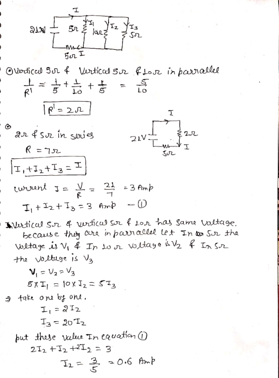
4. What is the current in the 10-2 resistor shown in the figure? 21 V 5Ω...
I 4. What is the current in the 10-Ω resistor shown in the figure? 10Ω 50...
 I 4. What is the current in the 10-Ω resistor shown in the figure? 10Ω 50 sa a. 0.60 A b. 3.0 A c. 1.2 A d. 24A e. 0.30A 7. A 20-V emf placed across a series combination of two resistors causes a current of 20 A in each of the resistors. If the same emf is placed across a parallel combination of the same two resistors and a current of 10 A through the emf is observed, what...
16) For the circuit shown in the figure, determine the current in (a) the 1.0-2 resistor....
 16) For the circuit shown in the figure, determine the current in (a) the 1.0-2 resistor. (b) the 3.0-Ω resistor. (c) the 4.0-Ω resistor. 2.0 Ω W 3.0 Ω 4.0 Ω, 12 V 5.0 Ω ΜΜΜ, 1.0 Ω
For the circuit shown, the voltage drop across the 5Ω resistor is measured as 10 V....
 For the circuit shown, the voltage drop across the 5Ω resistor is measured as 10 V. Determine the voltage provided by the source I. 3n. ラ ㄴ 2.n 1几
What is the current through the 10 ? resistor in the figure (Figure 1) ? Express...
 What is the current through the 10 ? resistor in the figure
(Figure 1) ? Express your answer to two significant figures and
include the appropriate units.
the answer is not 0.12 A
12V 5Ω 1oV 3 V 9 V
What is the current through the 10 ? resistor in the figure
(Figure 1) ? Express your answer to two significant figures and
include the appropriate units.
the answer is not 0.12 A
12V 5Ω 1oV 3 V 9 V
Find the current through the 6.0 Q resistor in the figure shown below. (Take R1 R2...
 Find the current through the 6.0 Q resistor in the figure shown below. (Take R1 R2 = 1.1 Q = 3.0 Q and E = 18.0 V.) 3.0 5 6.0 Answer: Ly
Problem 28.63 Part A What is the current through the 10 Ω resistor in the figure...
 Problem 28.63 Part A What is the current through the 10 Ω resistor in the figure (Figure 1)? Express your answer to two significant figures and include the appropriate units oa Value Units Figure 1 1 of 1 Submit My Answers Give Up Part B Is the current from left to right or right to left? 12V 5Ω left to right right to left 1012 3 V Submit My Answers Give Up Provide Feedback Continue 9 V
2. Use Node Analysis to find the current is 5Ω u2 U) 10 V 5Ω 10Ω...
 2. Use Node Analysis to find the current is 5Ω u2 U) 10 V 5Ω 10Ω 3A
factor of tW 10. A loop of wire shown on the figure for problem 10 is...
 factor of tW 10. A loop of wire shown on the figure for problem 10 is placed in a uniform magnetic field directed into the page. The area of the loop decreases by a factor of three during a time interval of one second. 21) The magnetic flux through the loop a) increases by a factor b) increases by a of three c) decreases by a factor of three d) decreases by a f of nine factor of nine 22)...
Using mesh current analysis, what is the current I1 in the following circuit below. 10Ω 5Ω Ο 10 V 20 V 1Α 10Ω 5Ω Ο...
 Using mesh current analysis,
what is the current I1 in the following circuit below.
10Ω 5Ω Ο 10 V 20 V 1Α
10Ω 5Ω Ο 10 V 20 V 1Α
Using mesh current analysis,
what is the current I1 in the following circuit below.
10Ω 5Ω Ο 10 V 20 V 1Α
10Ω 5Ω Ο 10 V 20 V 1Α
4. Three 100 Sresistors are connected, as shown in Figure 4. The maximum power that can...
 4. Three 100 Sresistors are connected, as shown in Figure 4. The maximum power that can safely be dissipated in any one resistor is 26.5 W. (a) What is the maximum voltage that can be applied to the terminals a and b? (b) For the voltage determined in part (a), what is the power dissipated in each resistor? (c) What is the total power dissipation? 5. A battery has an emf of 15.0 V. The terminal voltage of the battery...
 I 4. What is the current in the 10-Ω resistor shown in the figure? 10Ω 50 sa a. 0.60 A b. 3.0 A c. 1.2 A d. 24A e. 0.30A 7. A 20-V emf placed across a series combination of two resistors causes a current of 20 A in each of the resistors. If the same emf is placed across a parallel combination of the same two resistors and a current of 10 A through the emf is observed, what...
 16) For the circuit shown in the figure, determine the current in (a) the 1.0-2 resistor. (b) the 3.0-Ω resistor. (c) the 4.0-Ω resistor. 2.0 Ω W 3.0 Ω 4.0 Ω, 12 V 5.0 Ω ΜΜΜ, 1.0 Ω
 For the circuit shown, the voltage drop across the 5Ω resistor is measured as 10 V. Determine the voltage provided by the source I. 3n. ラ ㄴ 2.n 1几
 What is the current through the 10 ? resistor in the figure
(Figure 1) ? Express your answer to two significant figures and
include the appropriate units.
the answer is not 0.12 A
12V 5Ω 1oV 3 V 9 V
What is the current through the 10 ? resistor in the figure
(Figure 1) ? Express your answer to two significant figures and
include the appropriate units.
the answer is not 0.12 A
12V 5Ω 1oV 3 V 9 V
 Find the current through the 6.0 Q resistor in the figure shown below. (Take R1 R2 = 1.1 Q = 3.0 Q and E = 18.0 V.) 3.0 5 6.0 Answer: Ly
 Problem 28.63 Part A What is the current through the 10 Ω resistor in the figure (Figure 1)? Express your answer to two significant figures and include the appropriate units oa Value Units Figure 1 1 of 1 Submit My Answers Give Up Part B Is the current from left to right or right to left? 12V 5Ω left to right right to left 1012 3 V Submit My Answers Give Up Provide Feedback Continue 9 V
 2. Use Node Analysis to find the current is 5Ω u2 U) 10 V 5Ω 10Ω 3A
 factor of tW 10. A loop of wire shown on the figure for problem 10 is placed in a uniform magnetic field directed into the page. The area of the loop decreases by a factor of three during a time interval of one second. 21) The magnetic flux through the loop a) increases by a factor b) increases by a of three c) decreases by a factor of three d) decreases by a f of nine factor of nine 22)...
 Using mesh current analysis,
what is the current I1 in the following circuit below.
10Ω 5Ω Ο 10 V 20 V 1Α
10Ω 5Ω Ο 10 V 20 V 1Α
Using mesh current analysis,
what is the current I1 in the following circuit below.
10Ω 5Ω Ο 10 V 20 V 1Α
10Ω 5Ω Ο 10 V 20 V 1Α
 4. Three 100 Sresistors are connected, as shown in Figure 4. The maximum power that can safely be dissipated in any one resistor is 26.5 W. (a) What is the maximum voltage that can be applied to the terminals a and b? (b) For the voltage determined in part (a), what is the power dissipated in each resistor? (c) What is the total power dissipation? 5. A battery has an emf of 15.0 V. The terminal voltage of the battery...
Most questions answered within 3 hours.
-
Create a 32-run crossed array design with six control factors
and two noise factors such that...
asked 33 minutes ago -
A 500g sample of sand from source A has the following amounts
retained on each sieve....
asked 35 minutes ago -
In
your own words, please explain the essay by John Keynes wrote "The
End of Laissez...
asked 34 minutes ago -
How are the matrix and pixels related? Why are smaller
pixels better for diagnostic quality?
asked 37 minutes ago -
2. An AC generator has 80 rectangular loops on
its armature. Each loop is 11 cm...
asked 38 minutes ago -
Please help me with this question. Consider Aldi’s current and
potential geographic markets (see Exhibit 4...
asked 41 minutes ago -
What are the main components of the fermentation process and
give an explanation of each? Include...
asked 1 hour ago -
Explain which types of cells in the body (belonging to which
organs, etc.) are sensitive to...
asked 1 hour ago -
A single cable supports an 703-kg elevator car. What is the
tension in the cable when...
asked 1 hour ago -
among the three different ways to link CSS specifications to an
HTML document (inline CSS, document...
asked 1 hour ago -
(1) Write the net ionic equation for the reaction that occurs
when equal volumes of 0.191...
asked 1 hour ago -
On the night of April 18, 1775, a signal was to be sent from the
Old...
asked 1 hour ago