Often you need to make an estimate of the forces where you would not have time or tools to perform a detailed analysis. In this module, we will discuss methods for estimating loads or other statics results on rigid bodies. The Free Body Diagram is a good tool for estimation as you can visually add forces and moments. You can round given force values to one or 2 places of precision. You can also approximate centroids and centers of gravity by visual integration of the largest areas. For 2nd Moment of area and moment of inertia adjust for things further from the axis having more weight.
An example is below:
For the beam loaded and supported as shown approximate the reactions at A and B.
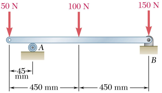
The 50 N load is close to support A so add 50 the reaction at A.
The 100 N load is about the middle of the beam so add 50 to both reactions.
The 150 N load is above support B so all of it gets transferred to B.
Reaction at A is approximately 100 N and reaction at B is approximately 200 N.
The reaction at A will be slightly greater and the reaction at B will be slightly less than the estimates.
Note that estimation is more of an art than a science so there is not a set procedure. Just apply logic and what you know about statics.
Assignment:
There are two problems listed below. Approximate, the solutions for both problems and describe how you approximated the solutions. An approximation is usually only one or two digits in accuracy. YOU ARE NOT TO COMPLETELY SOLVE THE PROBLEM. THESE SHOULD BE EDUCATED APPROXIMATIONS.
A) 
B) 
Homework Answers

![迁ー七ヴㅊ 8 and 3in 8 8 at [4]](http://img.homeworklib.com/questions/11336b60-73bb-11ea-95e1-67f17343ba87.png?x-oss-process=image/resize,w_560)

Add Answer to:
Often you need to make an estimate of the forces where you would
not have time...
Often you need to make an estimate of the forces where you would not have time...
 Often you need to make an estimate of the forces where you would
not have time or tools to perform a detailed analysis. In this
module, we will discuss methods for estimating loads or other
statics results on rigid bodies. The Free Body Diagram
is a good tool for estimation as you can visually add forces and
moments. You can round given force values to one or 2 places of
precision. You can also approximate centroids and centers of
gravity by...
Often you need to make an estimate of the forces where you would
not have time or tools to perform a detailed analysis. In this
module, we will discuss methods for estimating loads or other
statics results on rigid bodies. The Free Body Diagram
is a good tool for estimation as you can visually add forces and
moments. You can round given force values to one or 2 places of
precision. You can also approximate centroids and centers of
gravity by...
Determine the reaction forces at A and B 50 N 50 N 2n 80 N 160 N 240 N 15 N 30 N 60 N We have studied static equilibrium of forces acting at a common point, and static equilibrium of forces not...
 Determine the reaction forces at A and B 50 N 50 N 2n 80 N 160 N 240 N 15 N 30 N 60 N We have studied static equilibrium of forces acting at a common point, and static equilibrium of forces not acting at a common point but involving moments. Now, we will study static equilibrium of entire objects, with the underlying assumption that the objects cannot move nor change shape. These objects are called rigid bodies. We will...
Need help with E and F please. 3. The beam shown in the figure below is...
 Need help with E and F please.
3. The beam shown in the figure below is carrying superimposed dead load of 25 kN/m and use and occupancy load of 45 kN/m. For preliminary analysis, assume a self weight of 10 kN/m. We are required to find the maximum positive (tension at the bottom) and negative (tension at the top) moments due to the factored loads, and then design the beam CIV E 374-RC-Lab 3 Fall 2018 (a) Determine the maximum...
Need help with E and F please.
3. The beam shown in the figure below is carrying superimposed dead load of 25 kN/m and use and occupancy load of 45 kN/m. For preliminary analysis, assume a self weight of 10 kN/m. We are required to find the maximum positive (tension at the bottom) and negative (tension at the top) moments due to the factored loads, and then design the beam CIV E 374-RC-Lab 3 Fall 2018 (a) Determine the maximum...
ques1 ques 2 pls, help asap, make sure you all understood. Wrong ans give bad rate!...
 ques1
ques 2
pls, help asap, make sure you all understood. Wrong ans give
bad rate!
A weight is supported on a beam as shown. Determine the tension in the cable T. (3) T cable 450 beam 200kg 3m 7m A roof structure is made from trusses as shown in the figure below. 30 KN 450 45° 450 45° & 40 4 in G F 1 m 41 000 40 KN 60 KN 30 KN Calculate the reaction forces at...
ques1
ques 2
pls, help asap, make sure you all understood. Wrong ans give
bad rate!
A weight is supported on a beam as shown. Determine the tension in the cable T. (3) T cable 450 beam 200kg 3m 7m A roof structure is made from trusses as shown in the figure below. 30 KN 450 45° 450 45° & 40 4 in G F 1 m 41 000 40 KN 60 KN 30 KN Calculate the reaction forces at...
QUESTION 1 [25 marks A frame loaded with a uniformly distributed load at Member AB and...
 QUESTION 1 [25 marks A frame loaded with a uniformly distributed load at Member AB and point load at Member BC and joint B. It has pinned supports A and C, while joint B is fixed connected, as can be seen in Figure 1. Take E-200 GPa. a) Using the slope-deflection method, calculate the moments and illustrate the bending moment diagram. [15 marks) b) Then calculate the shear forces and sketch the shear force diagram. [10 marks) 22 KN 10...
Determ ine the internal forces at point J for the structure shown, where member BD can...
 Determ ine the internal forces at point J for the structure shown, where member BD can only carry axial forces. Take the dimension a 176 mm and the external load P 500 M a mm 225 mm B 120 mm 225 mm A P NV 135 mm axial force: Number Units (tolerance 1 N, magnitude only) FJ shear force: SF= Number Units (tolerance 1 N, magnitude only) bending moment Number Units (tolerance 100 N mm, magnitude only) BMJ
Determ ine...
Determ ine the internal forces at point J for the structure shown, where member BD can only carry axial forces. Take the dimension a 176 mm and the external load P 500 M a mm 225 mm B 120 mm 225 mm A P NV 135 mm axial force: Number Units (tolerance 1 N, magnitude only) FJ shear force: SF= Number Units (tolerance 1 N, magnitude only) bending moment Number Units (tolerance 100 N mm, magnitude only) BMJ
Determ ine...
please do all the parts clearly and accurately (20) The square beam AB, of length, L,...
 please do all the parts clearly and accurately
(20) The square beam AB, of length, L, and helght, h, in Fig. P3 is made of steel with an elastic modulus of E. Beam AB has an area moment of inertia, 1. A distributed load, w, is applied along the entire length. Note: The length is very large compared to the cross-sectional dimensions of the beam. Thus, assume bending loadings dominate Logically walk through the steps as requested in parts at...
please do all the parts clearly and accurately
(20) The square beam AB, of length, L, and helght, h, in Fig. P3 is made of steel with an elastic modulus of E. Beam AB has an area moment of inertia, 1. A distributed load, w, is applied along the entire length. Note: The length is very large compared to the cross-sectional dimensions of the beam. Thus, assume bending loadings dominate Logically walk through the steps as requested in parts at...
solve 1 and 3 please Wut unte. 02/06/2020, 12:00pm) Problem 1 (50 pts): For the beam...
 solve 1 and 3 please
Wut unte. 02/06/2020, 12:00pm) Problem 1 (50 pts): For the beam shown, a) Determine the reaction forces at the supports b) Derive the loading, shear-force, and bending moment relationships (g(x), and c) Draw the V(x) and M(x) graphs and identify the locations of the maximum shear force and bending moment along the beam d) Determine the maximum tensile and compressive stresses e) Determine the maximum shear stress due to V 13 kN 50 mm --...
solve 1 and 3 please
Wut unte. 02/06/2020, 12:00pm) Problem 1 (50 pts): For the beam shown, a) Determine the reaction forces at the supports b) Derive the loading, shear-force, and bending moment relationships (g(x), and c) Draw the V(x) and M(x) graphs and identify the locations of the maximum shear force and bending moment along the beam d) Determine the maximum tensile and compressive stresses e) Determine the maximum shear stress due to V 13 kN 50 mm --...
An existing building in Amman has been renovated. As a structural engineer, you are requested to...
 An existing building in Amman has been renovated. As a structural engineer, you are requested to check if the shown beam can hold the shown new loads. you are requested to do the following: A. A.1 Prepare all the shown details below after converting all the shown values to US customary units, in order to send it to the main design office that is located in the U.S. A.2 Calculate the resultant force and moments for all the loads shown...
Question I.5 Figure 1.5 shows a frame with loads at A and D. Select the closest...
 Question I.5 Figure 1.5 shows a frame with loads at A and D. Select the closest value for the magnitude of the total reaction at B. Assume the weight of the frame is zero. 40 kN VE 96.2 kN (a) (Ь -40 kN 5 m (c) -87.5 kN 30 kN (d) 57 kN 4m ao 1 m (e) 50 kN Figure L.5 Low mass frame Question I.6 In the shear and bending moment equations for beams, which of the following...
 Often you need to make an estimate of the forces where you would
not have time or tools to perform a detailed analysis. In this
module, we will discuss methods for estimating loads or other
statics results on rigid bodies. The Free Body Diagram
is a good tool for estimation as you can visually add forces and
moments. You can round given force values to one or 2 places of
precision. You can also approximate centroids and centers of
gravity by...
Often you need to make an estimate of the forces where you would
not have time or tools to perform a detailed analysis. In this
module, we will discuss methods for estimating loads or other
statics results on rigid bodies. The Free Body Diagram
is a good tool for estimation as you can visually add forces and
moments. You can round given force values to one or 2 places of
precision. You can also approximate centroids and centers of
gravity by...
 Determine the reaction forces at A and B 50 N 50 N 2n 80 N 160 N 240 N 15 N 30 N 60 N We have studied static equilibrium of forces acting at a common point, and static equilibrium of forces not acting at a common point but involving moments. Now, we will study static equilibrium of entire objects, with the underlying assumption that the objects cannot move nor change shape. These objects are called rigid bodies. We will...
 Need help with E and F please.
3. The beam shown in the figure below is carrying superimposed dead load of 25 kN/m and use and occupancy load of 45 kN/m. For preliminary analysis, assume a self weight of 10 kN/m. We are required to find the maximum positive (tension at the bottom) and negative (tension at the top) moments due to the factored loads, and then design the beam CIV E 374-RC-Lab 3 Fall 2018 (a) Determine the maximum...
Need help with E and F please.
3. The beam shown in the figure below is carrying superimposed dead load of 25 kN/m and use and occupancy load of 45 kN/m. For preliminary analysis, assume a self weight of 10 kN/m. We are required to find the maximum positive (tension at the bottom) and negative (tension at the top) moments due to the factored loads, and then design the beam CIV E 374-RC-Lab 3 Fall 2018 (a) Determine the maximum...
 ques1
ques 2
pls, help asap, make sure you all understood. Wrong ans give
bad rate!
A weight is supported on a beam as shown. Determine the tension in the cable T. (3) T cable 450 beam 200kg 3m 7m A roof structure is made from trusses as shown in the figure below. 30 KN 450 45° 450 45° & 40 4 in G F 1 m 41 000 40 KN 60 KN 30 KN Calculate the reaction forces at...
ques1
ques 2
pls, help asap, make sure you all understood. Wrong ans give
bad rate!
A weight is supported on a beam as shown. Determine the tension in the cable T. (3) T cable 450 beam 200kg 3m 7m A roof structure is made from trusses as shown in the figure below. 30 KN 450 45° 450 45° & 40 4 in G F 1 m 41 000 40 KN 60 KN 30 KN Calculate the reaction forces at...
 QUESTION 1 [25 marks A frame loaded with a uniformly distributed load at Member AB and point load at Member BC and joint B. It has pinned supports A and C, while joint B is fixed connected, as can be seen in Figure 1. Take E-200 GPa. a) Using the slope-deflection method, calculate the moments and illustrate the bending moment diagram. [15 marks) b) Then calculate the shear forces and sketch the shear force diagram. [10 marks) 22 KN 10...
 Determ ine the internal forces at point J for the structure shown, where member BD can only carry axial forces. Take the dimension a 176 mm and the external load P 500 M a mm 225 mm B 120 mm 225 mm A P NV 135 mm axial force: Number Units (tolerance 1 N, magnitude only) FJ shear force: SF= Number Units (tolerance 1 N, magnitude only) bending moment Number Units (tolerance 100 N mm, magnitude only) BMJ
Determ ine...
Determ ine the internal forces at point J for the structure shown, where member BD can only carry axial forces. Take the dimension a 176 mm and the external load P 500 M a mm 225 mm B 120 mm 225 mm A P NV 135 mm axial force: Number Units (tolerance 1 N, magnitude only) FJ shear force: SF= Number Units (tolerance 1 N, magnitude only) bending moment Number Units (tolerance 100 N mm, magnitude only) BMJ
Determ ine...
 please do all the parts clearly and accurately
(20) The square beam AB, of length, L, and helght, h, in Fig. P3 is made of steel with an elastic modulus of E. Beam AB has an area moment of inertia, 1. A distributed load, w, is applied along the entire length. Note: The length is very large compared to the cross-sectional dimensions of the beam. Thus, assume bending loadings dominate Logically walk through the steps as requested in parts at...
please do all the parts clearly and accurately
(20) The square beam AB, of length, L, and helght, h, in Fig. P3 is made of steel with an elastic modulus of E. Beam AB has an area moment of inertia, 1. A distributed load, w, is applied along the entire length. Note: The length is very large compared to the cross-sectional dimensions of the beam. Thus, assume bending loadings dominate Logically walk through the steps as requested in parts at...
 solve 1 and 3 please
Wut unte. 02/06/2020, 12:00pm) Problem 1 (50 pts): For the beam shown, a) Determine the reaction forces at the supports b) Derive the loading, shear-force, and bending moment relationships (g(x), and c) Draw the V(x) and M(x) graphs and identify the locations of the maximum shear force and bending moment along the beam d) Determine the maximum tensile and compressive stresses e) Determine the maximum shear stress due to V 13 kN 50 mm --...
solve 1 and 3 please
Wut unte. 02/06/2020, 12:00pm) Problem 1 (50 pts): For the beam shown, a) Determine the reaction forces at the supports b) Derive the loading, shear-force, and bending moment relationships (g(x), and c) Draw the V(x) and M(x) graphs and identify the locations of the maximum shear force and bending moment along the beam d) Determine the maximum tensile and compressive stresses e) Determine the maximum shear stress due to V 13 kN 50 mm --...
 An existing building in Amman has been renovated. As a structural engineer, you are requested to check if the shown beam can hold the shown new loads. you are requested to do the following: A. A.1 Prepare all the shown details below after converting all the shown values to US customary units, in order to send it to the main design office that is located in the U.S. A.2 Calculate the resultant force and moments for all the loads shown...
 Question I.5 Figure 1.5 shows a frame with loads at A and D. Select the closest value for the magnitude of the total reaction at B. Assume the weight of the frame is zero. 40 kN VE 96.2 kN (a) (Ь -40 kN 5 m (c) -87.5 kN 30 kN (d) 57 kN 4m ao 1 m (e) 50 kN Figure L.5 Low mass frame Question I.6 In the shear and bending moment equations for beams, which of the following...
Most questions answered within 3 hours.
-
1.How large must the coefficient of static friction be between
the tires and the road if...
asked 12 minutes ago -
What is the time complexity (Big-O) of the following code?
class Main
{
// Recursive...
asked 11 minutes ago -
Economists look at any situation in terms of its component
parts: the people making decisions, the...
asked 17 minutes ago -
What is a population?
Select one:
a. All of the individual organisms belonging to the same...
asked 21 minutes ago -
You have a yeast cell culture with a concentration of 5x10^4
cells/ml. If you dilute this...
asked 25 minutes ago -
In which direction the Reaction goes? Show detailed process.
SeO3 + 2ClO2. + 2H3O <---> Se...
asked 39 minutes ago -
Unexposed silver halides are removed from photographic film when
they react with sodium thiosulfate
(Na2S2O3, called...
asked 39 minutes ago -
A 0.3054 gram sample of the mineral chalcopyrite (CuFeS2)
yielded 0.6525 gram BaSO4 precipitate. What is...
asked 39 minutes ago -
An short-seller in Tesla is worried the latest management
earnings forecast is too aggressive and the...
asked 1 hour ago -
Question 3 (1 point)
Fill in the blank. Speed Car Rental company found that the tire...
asked 1 hour ago -
1. A copper wire is 26.61 cm long and weighs 1.265 g. The
density of copper...
asked 1 hour ago -
Remember that a concept sketch consists of a sketch (or
series of sketches), labels, and complete...
asked 1 hour ago