Determine the forces acting on the members
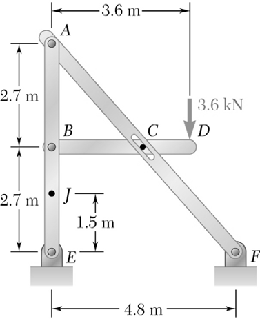
The member ACF of the frame loaded as shown is connected to the member BCD by means of a smooth peg and slot arrangement. Determine all the forces acting on themembers BCD and ACF.
(Ax = Fx = 3.04 kN, Ay = Fy = 2.7 kN; Bx = 6.08 kN; By = 1.8 kN; FC = 8.13 kN)
Please show your work.
Homework Answers

Determine the forces acting in all the members of the truss shown in Fig. 6–9a ....
 Determine the forces acting in all the members of the truss
shown in Fig. 6–9a
.
I need help understanding the bold parts below of
the solution. Please explain the methods/math involved with
steps:
Joint C
.Fx=0;
- FCD cos 30 + FCB sin 45=0
Fy=0;
1.5 kN + FCD sin 30 - FCB cos 45=0
These two equations must be solved simultaneously for
each of the two unknowns. Note, however, that a direct solution for
one of the unknown...
Determine the forces acting in all the members of the truss
shown in Fig. 6–9a
.
I need help understanding the bold parts below of
the solution. Please explain the methods/math involved with
steps:
Joint C
.Fx=0;
- FCD cos 30 + FCB sin 45=0
Fy=0;
1.5 kN + FCD sin 30 - FCB cos 45=0
These two equations must be solved simultaneously for
each of the two unknowns. Note, however, that a direct solution for
one of the unknown...
Example: Determine the forces acting on all members of the frame shown below 4 m 8...
 Example: Determine the forces acting on all members of the frame shown below 4 m 8 m 3 kN E 3 m 5 m 4 kN 2 kN 10 m 5 kN.m 3 kN.m A B 10 m
Example: Determine the forces acting on all members of the frame shown below 4 m 8 m 3 kN E 3 m 5 m 4 kN 2 kN 10 m 5 kN.m 3 kN.m A B 10 m
Example: Determine the forces acting on all members of the frame shown below 4 m 8 m 3 kN E 3 m 5 m 4 kN 2 kN 10 m 5 kN.m 3 kN.m A B 10 m
2. For the truss shown, determine the forces acting upon the members BC, FC and FE...
 2. For the truss shown, determine the forces acting upon the members BC, FC and FE by using the method of sections o1 IO KN 5 RN
Fx Fx Fy W EX OD Slot Ах Вх The given frame is subject to a...
 Fx Fx Fy W EX OD Slot Ах Вх The given frame is subject to a distributed load w = 55 kN/m and a horizontal force P = 20 kN. The free body diagrams for members AF and BF are also given. Assume L = 12 m, a = 10 m, b = 10 m, c = 14 m, and d = 2 m for your calculations. Determine reactions at supports A and B and the forces at pin F....
4-34 Refer to Fig. P4-34. Determine the forces acting on each member of the frame due...
 4-34 Refer to Fig. P4-34. Determine the forces acting on each member of the frame due to the 4-kN load shown. Neglect the weights of all members srwoda bsol 10 m 0.5 m 0.5m 4 kN 0.7 m FIGURE P4-34
6.32 through 6.38 Determine the components of the forces acting on each member of the pin-connected...
 6.32 through 6.38 Determine the components of the forces acting on each member of the pin-connected frame shown. r = 1 ft 4 ft 3 ft 2 ft Joha 2.0 kip - 4 f 4 ft PROB. 6.37
Q.3) In the frame shown, members AB, BC, CD, DEF and AF are pin-connected and supported by rollens at C, F and a pin support at D. Det ermine all support reactions and forces acting on members DE...
 Q.3) In the frame shown, members AB, BC, CD, DEF and AF are pin-connected and supported by rollens at C, F and a pin support at D. Det ermine all support reactions and forces acting on members DEP and DC 2 3 kN/m 10. 2 m 2 m 2
Q.3) In the frame shown, members AB, BC, CD, DEF and AF are pin-connected and supported by rollens at C, F and a pin support at D. Det ermine all support...
Q.3) In the frame shown, members AB, BC, CD, DEF and AF are pin-connected and supported by rollens at C, F and a pin support at D. Det ermine all support reactions and forces acting on members DEP and DC 2 3 kN/m 10. 2 m 2 m 2
Q.3) In the frame shown, members AB, BC, CD, DEF and AF are pin-connected and supported by rollens at C, F and a pin support at D. Det ermine all support...
 Determine the forces acting in all the members of the truss
shown in Fig. 6–9a
.
I need help understanding the bold parts below of
the solution. Please explain the methods/math involved with
steps:
Joint C
.Fx=0;
- FCD cos 30 + FCB sin 45=0
Fy=0;
1.5 kN + FCD sin 30 - FCB cos 45=0
These two equations must be solved simultaneously for
each of the two unknowns. Note, however, that a direct solution for
one of the unknown...
Determine the forces acting in all the members of the truss
shown in Fig. 6–9a
.
I need help understanding the bold parts below of
the solution. Please explain the methods/math involved with
steps:
Joint C
.Fx=0;
- FCD cos 30 + FCB sin 45=0
Fy=0;
1.5 kN + FCD sin 30 - FCB cos 45=0
These two equations must be solved simultaneously for
each of the two unknowns. Note, however, that a direct solution for
one of the unknown...
 Example: Determine the forces acting on all members of the frame shown below 4 m 8 m 3 kN E 3 m 5 m 4 kN 2 kN 10 m 5 kN.m 3 kN.m A B 10 m
Example: Determine the forces acting on all members of the frame shown below 4 m 8 m 3 kN E 3 m 5 m 4 kN 2 kN 10 m 5 kN.m 3 kN.m A B 10 m
Example: Determine the forces acting on all members of the frame shown below 4 m 8 m 3 kN E 3 m 5 m 4 kN 2 kN 10 m 5 kN.m 3 kN.m A B 10 m
 2. For the truss shown, determine the forces acting upon the members BC, FC and FE by using the method of sections o1 IO KN 5 RN
 Fx Fx Fy W EX OD Slot Ах Вх The given frame is subject to a distributed load w = 55 kN/m and a horizontal force P = 20 kN. The free body diagrams for members AF and BF are also given. Assume L = 12 m, a = 10 m, b = 10 m, c = 14 m, and d = 2 m for your calculations. Determine reactions at supports A and B and the forces at pin F....
 4-34 Refer to Fig. P4-34. Determine the forces acting on each member of the frame due to the 4-kN load shown. Neglect the weights of all members srwoda bsol 10 m 0.5 m 0.5m 4 kN 0.7 m FIGURE P4-34
 6.32 through 6.38 Determine the components of the forces acting on each member of the pin-connected frame shown. r = 1 ft 4 ft 3 ft 2 ft Joha 2.0 kip - 4 f 4 ft PROB. 6.37
 Q.3) In the frame shown, members AB, BC, CD, DEF and AF are pin-connected and supported by rollens at C, F and a pin support at D. Det ermine all support reactions and forces acting on members DEP and DC 2 3 kN/m 10. 2 m 2 m 2
Q.3) In the frame shown, members AB, BC, CD, DEF and AF are pin-connected and supported by rollens at C, F and a pin support at D. Det ermine all support...
Q.3) In the frame shown, members AB, BC, CD, DEF and AF are pin-connected and supported by rollens at C, F and a pin support at D. Det ermine all support reactions and forces acting on members DEP and DC 2 3 kN/m 10. 2 m 2 m 2
Q.3) In the frame shown, members AB, BC, CD, DEF and AF are pin-connected and supported by rollens at C, F and a pin support at D. Det ermine all support...
Most questions answered within 3 hours.
-
Calculate the pH of each of the following solutions.
0.50 M HBr
3.1×10⁻⁴ M KOH
4.2×10⁻⁵...
asked 1 hour ago -
For the year ended December 31, Depot Max’s cost of merchandise
sold was $85,600. Inventory at the...
asked 1 hour ago -
Week 10 - Professional Memo Assignment
Professional Memo Assignment
Your mission for this week, should you...
asked 1 hour ago -
Write a Python program that stores the data for each
player on the team, and it...
asked 1 hour ago -
In
the last 3 months, mike never knows when he is going to get his
allowance...
asked 2 hours ago -
Is Ca(OH)2 a Bronsted base, Lewis base, or both? Why?
asked 2 hours ago -
1A- Why don’t voters complain about U.S. tariffs on imported
sugar?
Because sugar is only a...
asked 2 hours ago -
Cash Payback Period
Primera Banco is evaluating two capital investment proposals for
a drive-up ATM kiosk,...
asked 2 hours ago -
Create a button in Swift (Xcode) that will create a charge,
create a charge using Stripe's...
asked 2 hours ago -
The reaction rate of CO and NO2 in the reaction
CO(g) + NO2(g) → CO2(g) +...
asked 2 hours ago -
Imagine that a chemist puts 6.40 mol each of
C3H8 and O2 in a 1.00-L container...
asked 2 hours ago -
How much money should be invested today in order to have $8340
at the end of...
asked 2 hours ago