
Homework Answers


Add Answer to:
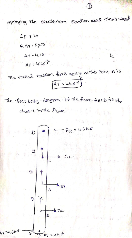
4-34 Refer to Fig. P4-34. Determine the forces acting on each member of the frame due...
Example: Determine the forces acting on all members of the frame shown below 4 m 8...
 Example: Determine the forces acting on all members of the frame shown below 4 m 8 m 3 kN E 3 m 5 m 4 kN 2 kN 10 m 5 kN.m 3 kN.m A B 10 m
Example: Determine the forces acting on all members of the frame shown below 4 m 8 m 3 kN E 3 m 5 m 4 kN 2 kN 10 m 5 kN.m 3 kN.m A B 10 m
Example: Determine the forces acting on all members of the frame shown below 4 m 8 m 3 kN E 3 m 5 m 4 kN 2 kN 10 m 5 kN.m 3 kN.m A B 10 m
Use moment distribution method or slope deflection method. The frame shown if Fig. 2.1 is supporting...
 Use moment distribution method or slope deflection
method.
The frame shown if Fig. 2.1 is supporting a lateral load of 60 kN and a gravity load of 50 kNIm. Neglect the weight of the members (a) Determine th reaction forces. (b) Draw the axial, shear, and bending moment and qualitative deflected shape diagrams of the frame. Specify values at a change of loading positions and at all points of zero shear and moment. Use slope-deflection method 2m Fig. 2.1 w...
Use moment distribution method or slope deflection
method.
The frame shown if Fig. 2.1 is supporting a lateral load of 60 kN and a gravity load of 50 kNIm. Neglect the weight of the members (a) Determine th reaction forces. (b) Draw the axial, shear, and bending moment and qualitative deflected shape diagrams of the frame. Specify values at a change of loading positions and at all points of zero shear and moment. Use slope-deflection method 2m Fig. 2.1 w...
PROBLEMS Section 4-4 Method of Joints 4-1 to 4-10 Refer to Figs. P4-1 to P4-10. Determine...
 PROBLEMS Section 4-4 Method of Joints 4-1 to 4-10 Refer to Figs. P4-1 to P4-10. Determine the forces in all members of the trusses shown using the method of joints. Indicate the results on the truss diagram using the arrow sign convention 76 KN 16 kN 2 m FIGURE P4-4
If P = 40 kN, determine the internal forces acting on each member of the cantilever...
 If P = 40 kN, determine the internal forces acting on each
member of the cantilever truss below.
PROBLEM 4 If P = 40 kN, determine the internal forces acting on each member of the cantilever truss below. (35) D E 1.50 m A B 2.0 m 2.0 m 0.5P P
If P = 40 kN, determine the internal forces acting on each
member of the cantilever truss below.
PROBLEM 4 If P = 40 kN, determine the internal forces acting on each member of the cantilever truss below. (35) D E 1.50 m A B 2.0 m 2.0 m 0.5P P
03: Given the statically indeterminate frame as shown in Fig. Q3 below, determine the member end...
 03: Given the statically indeterminate frame as shown in Fig. Q3 below, determine the member end moments and the support reactions of the frame using moment distribution method. Moment distribution to be done for 3 iterations of locking and unlocking cycle. A point load of 100KN is acting on span BC at 1/4 point of the span as shown. Support A and D are fixed supports. There is a roller support at joint C to prevent the frame from going...
Determine the forces acting on the members
 The member ACF of the frame loaded as shown is connected to the member BCD by means of a smooth peg and slot arrangement. Determine all the forces acting on themembers BCD and ACF.(Ax = Fx = 3.04 kN, Ay = Fy = 2.7 kN; Bx = 6.08 kN; By = 1.8 kN; FC = 8.13 kN)Please show your work.
6.32 through 6.38 Determine the components of the forces acting on each member of the pin-connected...
 6.32 through 6.38 Determine the components of the forces acting on each member of the pin-connected frame shown. r = 1 ft 4 ft 3 ft 2 ft Joha 2.0 kip - 4 f 4 ft PROB. 6.37
6.10 reactions and all internal forces 3m 6.9 and 6.10 Determine the force in each member...
 6.10
reactions and all internal forces
3m 6.9 and 6.10 Determine the force in each member of the truss shown. State whether each member is in tension (1) or compression (C). A 12.5 kN 12.5 kN 12.5 kN 12.5 KN 8 KN Fig. P6.9 2.5 m Fig. P6.10 6.11 Determine the force in each member of the Gambrel roof truss shown. State whether each member is in tension (T) or compression (C). 600 lb 600 lb 600 lb 2 ft...
6.10
reactions and all internal forces
3m 6.9 and 6.10 Determine the force in each member of the truss shown. State whether each member is in tension (1) or compression (C). A 12.5 kN 12.5 kN 12.5 kN 12.5 KN 8 KN Fig. P6.9 2.5 m Fig. P6.10 6.11 Determine the force in each member of the Gambrel roof truss shown. State whether each member is in tension (T) or compression (C). 600 lb 600 lb 600 lb 2 ft...
3. For the single-storey braced frame shown below, determine the design axial loads of the members...
 3. For the single-storey braced frame shown below, determine the design axial loads of the members under gravity plus wind loads. All the members are pinned-connected and the self- weights of the member are included in the dead load. в, Vw Ps 200 kN V,-50 kN 6.0 m
Q7) Find the member forces in the truss shown in Fig.7 using method of Consistent Deformations....
 Q7) Find the member forces in the truss shown in Fig.7 using method of Consistent Deformations. Assume "AE "is constant for all the members. 120 kN 12 ft 9 ft Figure 7
 Example: Determine the forces acting on all members of the frame shown below 4 m 8 m 3 kN E 3 m 5 m 4 kN 2 kN 10 m 5 kN.m 3 kN.m A B 10 m
Example: Determine the forces acting on all members of the frame shown below 4 m 8 m 3 kN E 3 m 5 m 4 kN 2 kN 10 m 5 kN.m 3 kN.m A B 10 m
Example: Determine the forces acting on all members of the frame shown below 4 m 8 m 3 kN E 3 m 5 m 4 kN 2 kN 10 m 5 kN.m 3 kN.m A B 10 m
 Use moment distribution method or slope deflection
method.
The frame shown if Fig. 2.1 is supporting a lateral load of 60 kN and a gravity load of 50 kNIm. Neglect the weight of the members (a) Determine th reaction forces. (b) Draw the axial, shear, and bending moment and qualitative deflected shape diagrams of the frame. Specify values at a change of loading positions and at all points of zero shear and moment. Use slope-deflection method 2m Fig. 2.1 w...
Use moment distribution method or slope deflection
method.
The frame shown if Fig. 2.1 is supporting a lateral load of 60 kN and a gravity load of 50 kNIm. Neglect the weight of the members (a) Determine th reaction forces. (b) Draw the axial, shear, and bending moment and qualitative deflected shape diagrams of the frame. Specify values at a change of loading positions and at all points of zero shear and moment. Use slope-deflection method 2m Fig. 2.1 w...
 PROBLEMS Section 4-4 Method of Joints 4-1 to 4-10 Refer to Figs. P4-1 to P4-10. Determine the forces in all members of the trusses shown using the method of joints. Indicate the results on the truss diagram using the arrow sign convention 76 KN 16 kN 2 m FIGURE P4-4
 If P = 40 kN, determine the internal forces acting on each
member of the cantilever truss below.
PROBLEM 4 If P = 40 kN, determine the internal forces acting on each member of the cantilever truss below. (35) D E 1.50 m A B 2.0 m 2.0 m 0.5P P
If P = 40 kN, determine the internal forces acting on each
member of the cantilever truss below.
PROBLEM 4 If P = 40 kN, determine the internal forces acting on each member of the cantilever truss below. (35) D E 1.50 m A B 2.0 m 2.0 m 0.5P P
 03: Given the statically indeterminate frame as shown in Fig. Q3 below, determine the member end moments and the support reactions of the frame using moment distribution method. Moment distribution to be done for 3 iterations of locking and unlocking cycle. A point load of 100KN is acting on span BC at 1/4 point of the span as shown. Support A and D are fixed supports. There is a roller support at joint C to prevent the frame from going...
 The member ACF of the frame loaded as shown is connected to the member BCD by means of a smooth peg and slot arrangement. Determine all the forces acting on themembers BCD and ACF.(Ax = Fx = 3.04 kN, Ay = Fy = 2.7 kN; Bx = 6.08 kN; By = 1.8 kN; FC = 8.13 kN)Please show your work.
 6.32 through 6.38 Determine the components of the forces acting on each member of the pin-connected frame shown. r = 1 ft 4 ft 3 ft 2 ft Joha 2.0 kip - 4 f 4 ft PROB. 6.37
 6.10
reactions and all internal forces
3m 6.9 and 6.10 Determine the force in each member of the truss shown. State whether each member is in tension (1) or compression (C). A 12.5 kN 12.5 kN 12.5 kN 12.5 KN 8 KN Fig. P6.9 2.5 m Fig. P6.10 6.11 Determine the force in each member of the Gambrel roof truss shown. State whether each member is in tension (T) or compression (C). 600 lb 600 lb 600 lb 2 ft...
6.10
reactions and all internal forces
3m 6.9 and 6.10 Determine the force in each member of the truss shown. State whether each member is in tension (1) or compression (C). A 12.5 kN 12.5 kN 12.5 kN 12.5 KN 8 KN Fig. P6.9 2.5 m Fig. P6.10 6.11 Determine the force in each member of the Gambrel roof truss shown. State whether each member is in tension (T) or compression (C). 600 lb 600 lb 600 lb 2 ft...
 3. For the single-storey braced frame shown below, determine the design axial loads of the members under gravity plus wind loads. All the members are pinned-connected and the self- weights of the member are included in the dead load. в, Vw Ps 200 kN V,-50 kN 6.0 m
 Q7) Find the member forces in the truss shown in Fig.7 using method of Consistent Deformations. Assume "AE "is constant for all the members. 120 kN 12 ft 9 ft Figure 7
Most questions answered within 3 hours.
-
Coding in C. Please only use stdio.h (which would mean no malloc
or anything like that)...
asked 12 seconds ago -
A sample of n = 25 scores produces a t statistic of t =
-2.062. If...
asked 1 minute ago -
A population has a mean of 200 and a standard deviation of 60.
Suppose a sample...
asked 2 minutes ago -
A bicyclist starting at rest produces a constant angular
acceleration of 1.10 rad/s2 for wheels that...
asked 16 minutes ago -
The
half-life of a radioactive source is 14.0 minutes. How much time
must elapse before the...
asked 14 minutes ago -
Given P(Ec ) = 0.43, P(F) = 0.52, and P(EF) = 0.18.
Find P( E |...
asked 1 hour ago -
Consider two empty containers A and B whose volumes are
10mL and 20mL respectively. 1mL of...
asked 1 hour ago -
QUESTION 6
Determine the linear momentum of a 2,800 kg houseboat going 3
m/s.
9,100 kg.m/s...
asked 1 hour ago -
Jor-el throws a ball upward from the top of a 728 foot building
on the planet...
asked 1 hour ago -
Which of the following will most likely to happen if Federal
Reserve Bank decreases the money...
asked 1 hour ago -
You’ve just joined the investment banking firm of Dewey,
Cheatum, and Howe. They’ve offered you two...
asked 59 minutes ago -
An air conditioner cools 226 m^3/min of humid air at 36 oC and
98% relative humidity...
asked 58 minutes ago