


Homework Answers


Add Answer to:
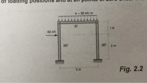
Use moment distribution method or slope deflection
method.
The frame shown if Fig. 2.1 is supporting...
For the frame shown. use the slope-deflection method to (a) Determine the end moments of each...
 For the frame shown. use the slope-deflection method to (a) Determine the end moments of each member and reactions at supports (b) Draw the quantitative bending moment diagram. and also draw the qualitative deflected shape of the entire frame. 10 kN 12 kN/m 2EI 3 m 40 KN 3 m 6 m
Need a solution for slope-deflection method Question 2 (20 marks) Use the Slope-Deflection Method to analyse...
 Need a solution for slope-deflection method
Question 2 (20 marks) Use the Slope-Deflection Method to analyse the frame in Figure 2. Plot diagrams for internal forces (M, V and N). Indicate magnitudes at all significant points. The bending stiffness of members is indicated in the figure. Neglect the effect of shear and axial forces on the structural deformations. 90 kNm 24 kN/m B v 64 kN a, 4m 2m ទឹក 9m Sm A 2ET ZEL 201 6m E] &m E1...
Need a solution for slope-deflection method
Question 2 (20 marks) Use the Slope-Deflection Method to analyse the frame in Figure 2. Plot diagrams for internal forces (M, V and N). Indicate magnitudes at all significant points. The bending stiffness of members is indicated in the figure. Neglect the effect of shear and axial forces on the structural deformations. 90 kNm 24 kN/m B v 64 kN a, 4m 2m ទឹក 9m Sm A 2ET ZEL 201 6m E] &m E1...
Use the Slope-Deflection Method to analyse the structure of Figure 1 and draw the shear force, axial force, and bending moment diagrams 4 m (1.5 EI) 20 KN/m 10 KN/m 50 kN.m Figure 1 Use the Slop...
 Use the Slope-Deflection Method to analyse the structure of Figure 1 and draw the shear force, axial force, and bending moment diagrams 4 m (1.5 EI) 20 KN/m 10 KN/m 50 kN.m Figure 1
Use the Slope-Deflection Method to analyse the structure of Figure 1 and draw the shear force, axial force, and bending moment diagrams 4 m (1.5 EI) 20 KN/m 10 KN/m 50 kN.m Figure 1
Use the Slope-Deflection Method to analyse the structure of Figure 1 and draw the shear force, axial force, and bending moment diagrams 4 m (1.5 EI) 20 KN/m 10 KN/m 50 kN.m Figure 1
Use slope-deflection method to analyze the frame shown below. Segments AB and BD of the frame...
 Use slope-deflection method to analyze the frame shown below. Segments AB and BD of the frame have moment of inertia I. Segment BC has moment of inertia 2/. Modulus of elasticity E is constant throughout the frame. The frame is supported by fixed-supports at A and D, and by a roller-support at C. Joint B is rigid. A downward point load of 20 kN is applied at mid-span of AB. Uniformly distributed load of intensity 2 kN/m acting downwards is...
For the beam shown in Fig. 9.3, draw the shear force and bending moment diagrams. Use...
 For the beam shown in Fig. 9.3, draw the shear force and bending moment diagrams. Use the area method that relies on the relationships between loading and shear force and between shear force and bending moment. Indicate the slope of the shear force diagram at locations A, B, C, and D using the load information in Fig. 9.3. Indicate the slope of the bending moment diagram at the same four locations using information from the shear force diagram. | 6...
asap Q4: Using slope-deflection method, determine the reactions of the supports for the frame shown in...
 asap
Q4: Using slope-deflection method, determine the reactions of the supports for the frame shown in Figure (4). Then draw shear and bending moment diagrams for the frame. E is constant. 5k/ft E D 10 ft B-10k 5 ft -20 ft tsa -21 E = constant Fig. (4)
asap
Q4: Using slope-deflection method, determine the reactions of the supports for the frame shown in Figure (4). Then draw shear and bending moment diagrams for the frame. E is constant. 5k/ft E D 10 ft B-10k 5 ft -20 ft tsa -21 E = constant Fig. (4)
Analyze the frame shown in the figure using both Slope Deflection and Moment Distribution Methods Draw...
 Analyze the frame shown in the figure using both Slope
Deflection and Moment Distribution Methods
Draw the V, and M diagrams
20 kN/m SEI BEI CEI 2E1 2E1 3 m JE - 3 m - - 3 m - - 3 m - - a) Analyze the frame shown in the figure using both Slope Deflection and Moment Distribution Methods b) Draw the V, and M diagrams.
Analyze the frame shown in the figure using both Slope
Deflection and Moment Distribution Methods
Draw the V, and M diagrams
20 kN/m SEI BEI CEI 2E1 2E1 3 m JE - 3 m - - 3 m - - 3 m - - a) Analyze the frame shown in the figure using both Slope Deflection and Moment Distribution Methods b) Draw the V, and M diagrams.
Q4: Using slope-deflection method, determine the reactions of the supports for the frame shown in Figure...
 Q4: Using slope-deflection method, determine the reactions of the supports for the frame shown in Figure (4). Then draw shear and bending moment diagrams for the frame . E is constant 25% 5k/ E D 10 ft B-10k 5 ft ts -20 ft 51 -21 E = constant
Draw the shear and bending moment diagrams and the qualitative deflected shape for the beam shown in Fig. 5.10(a)
 Draw the shear and bending moment diagrams and the qualitative deflected shape for the beam shown in Fig. 5.10(a)
Q4: Using slope-deflection method, determine the reactions of the supports for the frame shown in Figure...
 Q4: Using slope-deflection method, determine the
reactions of the supports for the frame shown in Figure (4). Then
draw shear and bending moment diagrams for the frame . E is
constant.
I need it in 30min or 1 h
SA E DI 10 ft B-10 k 5 ft A 20 ft +5 Sft E = constant E
Q4: Using slope-deflection method, determine the
reactions of the supports for the frame shown in Figure (4). Then
draw shear and bending moment diagrams for the frame . E is
constant.
I need it in 30min or 1 h
SA E DI 10 ft B-10 k 5 ft A 20 ft +5 Sft E = constant E
 For the frame shown. use the slope-deflection method to (a) Determine the end moments of each member and reactions at supports (b) Draw the quantitative bending moment diagram. and also draw the qualitative deflected shape of the entire frame. 10 kN 12 kN/m 2EI 3 m 40 KN 3 m 6 m
 Need a solution for slope-deflection method
Question 2 (20 marks) Use the Slope-Deflection Method to analyse the frame in Figure 2. Plot diagrams for internal forces (M, V and N). Indicate magnitudes at all significant points. The bending stiffness of members is indicated in the figure. Neglect the effect of shear and axial forces on the structural deformations. 90 kNm 24 kN/m B v 64 kN a, 4m 2m ទឹក 9m Sm A 2ET ZEL 201 6m E] &m E1...
Need a solution for slope-deflection method
Question 2 (20 marks) Use the Slope-Deflection Method to analyse the frame in Figure 2. Plot diagrams for internal forces (M, V and N). Indicate magnitudes at all significant points. The bending stiffness of members is indicated in the figure. Neglect the effect of shear and axial forces on the structural deformations. 90 kNm 24 kN/m B v 64 kN a, 4m 2m ទឹក 9m Sm A 2ET ZEL 201 6m E] &m E1...
 Use the Slope-Deflection Method to analyse the structure of Figure 1 and draw the shear force, axial force, and bending moment diagrams 4 m (1.5 EI) 20 KN/m 10 KN/m 50 kN.m Figure 1
Use the Slope-Deflection Method to analyse the structure of Figure 1 and draw the shear force, axial force, and bending moment diagrams 4 m (1.5 EI) 20 KN/m 10 KN/m 50 kN.m Figure 1
Use the Slope-Deflection Method to analyse the structure of Figure 1 and draw the shear force, axial force, and bending moment diagrams 4 m (1.5 EI) 20 KN/m 10 KN/m 50 kN.m Figure 1
 Use slope-deflection method to analyze the frame shown below. Segments AB and BD of the frame have moment of inertia I. Segment BC has moment of inertia 2/. Modulus of elasticity E is constant throughout the frame. The frame is supported by fixed-supports at A and D, and by a roller-support at C. Joint B is rigid. A downward point load of 20 kN is applied at mid-span of AB. Uniformly distributed load of intensity 2 kN/m acting downwards is...
 For the beam shown in Fig. 9.3, draw the shear force and bending moment diagrams. Use the area method that relies on the relationships between loading and shear force and between shear force and bending moment. Indicate the slope of the shear force diagram at locations A, B, C, and D using the load information in Fig. 9.3. Indicate the slope of the bending moment diagram at the same four locations using information from the shear force diagram. | 6...
 asap
Q4: Using slope-deflection method, determine the reactions of the supports for the frame shown in Figure (4). Then draw shear and bending moment diagrams for the frame. E is constant. 5k/ft E D 10 ft B-10k 5 ft -20 ft tsa -21 E = constant Fig. (4)
asap
Q4: Using slope-deflection method, determine the reactions of the supports for the frame shown in Figure (4). Then draw shear and bending moment diagrams for the frame. E is constant. 5k/ft E D 10 ft B-10k 5 ft -20 ft tsa -21 E = constant Fig. (4)
 Analyze the frame shown in the figure using both Slope
Deflection and Moment Distribution Methods
Draw the V, and M diagrams
20 kN/m SEI BEI CEI 2E1 2E1 3 m JE - 3 m - - 3 m - - 3 m - - a) Analyze the frame shown in the figure using both Slope Deflection and Moment Distribution Methods b) Draw the V, and M diagrams.
Analyze the frame shown in the figure using both Slope
Deflection and Moment Distribution Methods
Draw the V, and M diagrams
20 kN/m SEI BEI CEI 2E1 2E1 3 m JE - 3 m - - 3 m - - 3 m - - a) Analyze the frame shown in the figure using both Slope Deflection and Moment Distribution Methods b) Draw the V, and M diagrams.
 Q4: Using slope-deflection method, determine the reactions of the supports for the frame shown in Figure (4). Then draw shear and bending moment diagrams for the frame . E is constant 25% 5k/ E D 10 ft B-10k 5 ft ts -20 ft 51 -21 E = constant
 Q4: Using slope-deflection method, determine the
reactions of the supports for the frame shown in Figure (4). Then
draw shear and bending moment diagrams for the frame . E is
constant.
I need it in 30min or 1 h
SA E DI 10 ft B-10 k 5 ft A 20 ft +5 Sft E = constant E
Q4: Using slope-deflection method, determine the
reactions of the supports for the frame shown in Figure (4). Then
draw shear and bending moment diagrams for the frame . E is
constant.
I need it in 30min or 1 h
SA E DI 10 ft B-10 k 5 ft A 20 ft +5 Sft E = constant E
Most questions answered within 3 hours.
-
A .15kg rubber ball is bounced off a wall. Before hitting the
wall, the ball moves...
asked 32 minutes ago -
A manufacturing company preparing to build a new plant is
considering three potential locations for it....
asked 33 minutes ago -
B. If compound Y has approximately the same values of solubility
in toluene as compound X,...
asked 1 hour ago -
Oscar Inc. has inventory in Japan valued at 39,051,000 Yen one
year ago. One year ago...
asked 1 hour ago -
If Canada suffered from "fundamental disequilibrium," and its
government choose not to devalue its currency, a...
asked 1 hour ago -
4. How many input & output Key Value Pairs are passed into,
and emitted out of...
asked 1 hour ago -
Why would your heart not function well if constructed of
skeletal muscle? What is the particular...
asked 1 hour ago -
Please respond to this essay question in full essay form for
Chemistry 1102 Organic and Biochemistry:...
asked 1 hour ago -
Determine the head loss and velocity of flow in a water supply main
of 15.0 cm...
asked 1 hour ago -
A marketing executive who knowingly authorizes a shoddy
defective product to be brought to market is...
asked 1 hour ago -
Write a psudocode:
1. Define a function called authorize that takes in 2 strings,
uName, and...
asked 1 hour ago -
What Hall voltage (in mV) is produced by a 0.180 T field applied
across a 2.60...
asked 1 hour ago