
Homework Answers
Add Answer to:
Use the Slope-Deflection Method to analyse the structure of Figure 1 and draw the shear force, axial force, and bending moment diagrams 4 m (1.5 EI) 20 KN/m 10 KN/m 50 kN.m Figure 1 Use the Slop...
draw axial force, shear force and bending moment diagrams 2m 4'm 30 kN 2m 50 kN...
 draw axial force, shear force and bending moment
diagrams
2m 4'm 30 kN 2m 50 kN 4m A 3 m 1m -3m 1.5m
draw axial force, shear force and bending moment
diagrams
2m 4'm 30 kN 2m 50 kN 4m A 3 m 1m -3m 1.5m
Question 1) (L.0.6.1-4): Using the force method, draw the bending moment, shear force and axial force...
 Question 1) (L.0.6.1-4): Using the force method, draw the bending moment, shear force and axial force diagrams for the structure shown in Figure 1. Effects of shear and axial forces on deformation are neglected. qa? B 2a Figure 1. Question 2) (L.0.7.1-4): Using the displacement method, draw the bending moment diagram for the structure shown in Figure 2. Effects of axial and shear forces on deformation are neglected. 2qa? q qa a/2 a/2 a a/2 a/2 f + Figure 2.
Need a solution for slope-deflection method Question 2 (20 marks) Use the Slope-Deflection Method to analyse...
 Need a solution for slope-deflection method
Question 2 (20 marks) Use the Slope-Deflection Method to analyse the frame in Figure 2. Plot diagrams for internal forces (M, V and N). Indicate magnitudes at all significant points. The bending stiffness of members is indicated in the figure. Neglect the effect of shear and axial forces on the structural deformations. 90 kNm 24 kN/m B v 64 kN a, 4m 2m ទឹក 9m Sm A 2ET ZEL 201 6m E] &m E1...
Need a solution for slope-deflection method
Question 2 (20 marks) Use the Slope-Deflection Method to analyse the frame in Figure 2. Plot diagrams for internal forces (M, V and N). Indicate magnitudes at all significant points. The bending stiffness of members is indicated in the figure. Neglect the effect of shear and axial forces on the structural deformations. 90 kNm 24 kN/m B v 64 kN a, 4m 2m ទឹក 9m Sm A 2ET ZEL 201 6m E] &m E1...
Use moment distribution method or slope deflection method. The frame shown if Fig. 2.1 is supporting...
 Use moment distribution method or slope deflection
method.
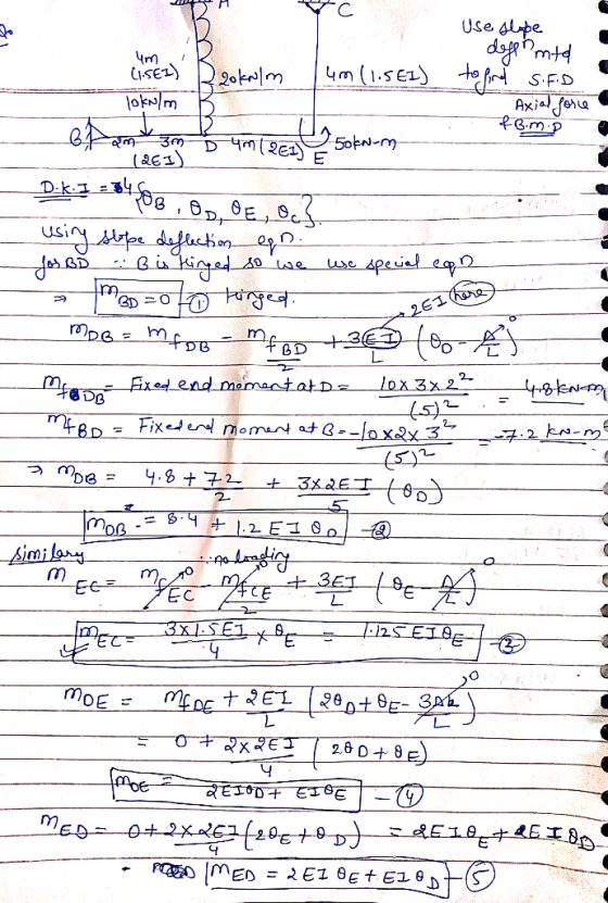
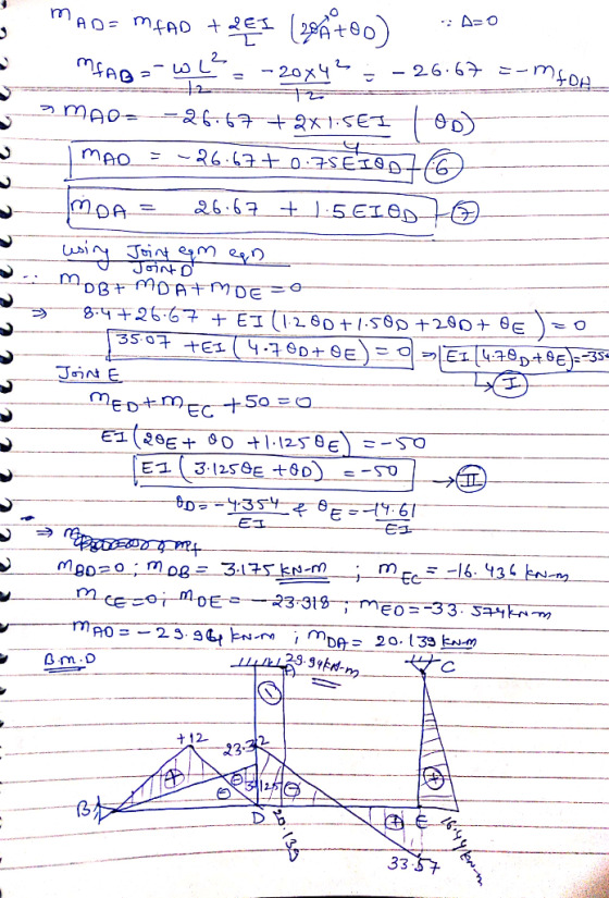
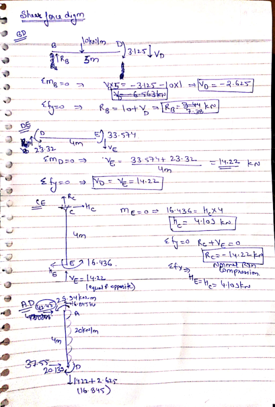
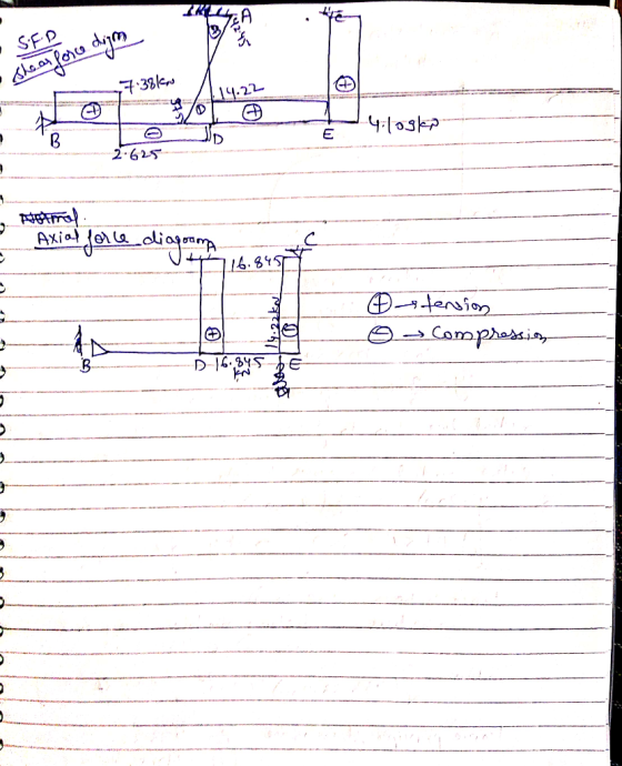
The frame shown if Fig. 2.1 is supporting a lateral load of 60 kN and a gravity load of 50 kNIm. Neglect the weight of the members (a) Determine th reaction forces. (b) Draw the axial, shear, and bending moment and qualitative deflected shape diagrams of the frame. Specify values at a change of loading positions and at all points of zero shear and moment. Use slope-deflection method 2m Fig. 2.1 w...
Use moment distribution method or slope deflection
method.
The frame shown if Fig. 2.1 is supporting a lateral load of 60 kN and a gravity load of 50 kNIm. Neglect the weight of the members (a) Determine th reaction forces. (b) Draw the axial, shear, and bending moment and qualitative deflected shape diagrams of the frame. Specify values at a change of loading positions and at all points of zero shear and moment. Use slope-deflection method 2m Fig. 2.1 w...
Draw the shear force and bending moment diagrams for the given beam. Use slope-deflection equations.
 Draw the shear force and bending moment diagrams for the given beam. Use slope-deflection equations.
(can be solve by slope deflection ) Using displacement method of analysis: (a) Draw bending moment...
 (can be solve by slope deflection )
Using displacement method of analysis: (a) Draw bending moment diagram; (b) Draw shear force diagram; (c) Draw axial force diagram; (d) Find nodal displacements and rotations at B and D. P=30 kn H=60 KN B EI DI EI E 1 2EI pin fixed 8m
(can be solve by slope deflection )
Using displacement method of analysis: (a) Draw bending moment diagram; (b) Draw shear force diagram; (c) Draw axial force diagram; (d) Find nodal displacements and rotations at B and D. P=30 kn H=60 KN B EI DI EI E 1 2EI pin fixed 8m
2 kN Draw the shear-force and bending-moment diagrams for the beam loaded by the 2-kN force...
 2 kN Draw the shear-force and bending-moment diagrams for the beam loaded by the 2-kN force and the 1.6 kN-m couple. State the value of the bending moment at point B. HW22-2 1.6 kN.m 0.5m 0.5 m 0.5 m
For the beam shown in Fig. 9.3, draw the shear force and bending moment diagrams. Use...
 For the beam shown in Fig. 9.3, draw the shear force and bending moment diagrams. Use the area method that relies on the relationships between loading and shear force and between shear force and bending moment. Indicate the slope of the shear force diagram at locations A, B, C, and D using the load information in Fig. 9.3. Indicate the slope of the bending moment diagram at the same four locations using information from the shear force diagram. | 6...
4. For the beam and loading shown, draw the shear force and bending moment diagrams and...
 4. For the beam and loading shown, draw the shear force and bending moment diagrams and determine the maximum bending and shear force and their locations. 20 KN 40 KN B D 250 mm |--2.5 m- 3m-4-2 m 80 mm 5. For the beam and loading shown, draw the shear force and bending moment diagrams and determine the maximum bending and shear force and their locations. 50 KN
Draw shear force and bending moment diagrams for the following, giving all principal values. 50 KN...
 Draw shear force and bending moment diagrams for the
following, giving all principal values.
50 KN 40 KN 20 AN 30 AN 50 kNm 2m 2m 20 N 20KN kNm 4 m 10 KN 2 m 3 m
Draw shear force and bending moment diagrams for the
following, giving all principal values.
50 KN 40 KN 20 AN 30 AN 50 kNm 2m 2m 20 N 20KN kNm 4 m 10 KN 2 m 3 m
 draw axial force, shear force and bending moment
diagrams
2m 4'm 30 kN 2m 50 kN 4m A 3 m 1m -3m 1.5m
draw axial force, shear force and bending moment
diagrams
2m 4'm 30 kN 2m 50 kN 4m A 3 m 1m -3m 1.5m
 Question 1) (L.0.6.1-4): Using the force method, draw the bending moment, shear force and axial force diagrams for the structure shown in Figure 1. Effects of shear and axial forces on deformation are neglected. qa? B 2a Figure 1. Question 2) (L.0.7.1-4): Using the displacement method, draw the bending moment diagram for the structure shown in Figure 2. Effects of axial and shear forces on deformation are neglected. 2qa? q qa a/2 a/2 a a/2 a/2 f + Figure 2.
 Need a solution for slope-deflection method
Question 2 (20 marks) Use the Slope-Deflection Method to analyse the frame in Figure 2. Plot diagrams for internal forces (M, V and N). Indicate magnitudes at all significant points. The bending stiffness of members is indicated in the figure. Neglect the effect of shear and axial forces on the structural deformations. 90 kNm 24 kN/m B v 64 kN a, 4m 2m ទឹក 9m Sm A 2ET ZEL 201 6m E] &m E1...
Need a solution for slope-deflection method
Question 2 (20 marks) Use the Slope-Deflection Method to analyse the frame in Figure 2. Plot diagrams for internal forces (M, V and N). Indicate magnitudes at all significant points. The bending stiffness of members is indicated in the figure. Neglect the effect of shear and axial forces on the structural deformations. 90 kNm 24 kN/m B v 64 kN a, 4m 2m ទឹក 9m Sm A 2ET ZEL 201 6m E] &m E1...
 Use moment distribution method or slope deflection
method.
The frame shown if Fig. 2.1 is supporting a lateral load of 60 kN and a gravity load of 50 kNIm. Neglect the weight of the members (a) Determine th reaction forces. (b) Draw the axial, shear, and bending moment and qualitative deflected shape diagrams of the frame. Specify values at a change of loading positions and at all points of zero shear and moment. Use slope-deflection method 2m Fig. 2.1 w...
Use moment distribution method or slope deflection
method.
The frame shown if Fig. 2.1 is supporting a lateral load of 60 kN and a gravity load of 50 kNIm. Neglect the weight of the members (a) Determine th reaction forces. (b) Draw the axial, shear, and bending moment and qualitative deflected shape diagrams of the frame. Specify values at a change of loading positions and at all points of zero shear and moment. Use slope-deflection method 2m Fig. 2.1 w...
 (can be solve by slope deflection )
Using displacement method of analysis: (a) Draw bending moment diagram; (b) Draw shear force diagram; (c) Draw axial force diagram; (d) Find nodal displacements and rotations at B and D. P=30 kn H=60 KN B EI DI EI E 1 2EI pin fixed 8m
(can be solve by slope deflection )
Using displacement method of analysis: (a) Draw bending moment diagram; (b) Draw shear force diagram; (c) Draw axial force diagram; (d) Find nodal displacements and rotations at B and D. P=30 kn H=60 KN B EI DI EI E 1 2EI pin fixed 8m
 2 kN Draw the shear-force and bending-moment diagrams for the beam loaded by the 2-kN force and the 1.6 kN-m couple. State the value of the bending moment at point B. HW22-2 1.6 kN.m 0.5m 0.5 m 0.5 m
 For the beam shown in Fig. 9.3, draw the shear force and bending moment diagrams. Use the area method that relies on the relationships between loading and shear force and between shear force and bending moment. Indicate the slope of the shear force diagram at locations A, B, C, and D using the load information in Fig. 9.3. Indicate the slope of the bending moment diagram at the same four locations using information from the shear force diagram. | 6...
 4. For the beam and loading shown, draw the shear force and bending moment diagrams and determine the maximum bending and shear force and their locations. 20 KN 40 KN B D 250 mm |--2.5 m- 3m-4-2 m 80 mm 5. For the beam and loading shown, draw the shear force and bending moment diagrams and determine the maximum bending and shear force and their locations. 50 KN
 Draw shear force and bending moment diagrams for the
following, giving all principal values.
50 KN 40 KN 20 AN 30 AN 50 kNm 2m 2m 20 N 20KN kNm 4 m 10 KN 2 m 3 m
Draw shear force and bending moment diagrams for the
following, giving all principal values.
50 KN 40 KN 20 AN 30 AN 50 kNm 2m 2m 20 N 20KN kNm 4 m 10 KN 2 m 3 m
Most questions answered within 3 hours.
-
Other decisions about scientific claims can have a much broader
impact.ENERGYarrow-10x10.png, environment, health, security - all...
asked 15 minutes ago -
I need to write a research paper and work cited about this
topic: The United States...
asked 38 minutes ago -
Hello! I was wondering if I could have some help?
If the vapor pressure of carvone...
asked 1 hour ago -
An economist wants to estimate the mean per capita income (in
thousands of dollars) for a...
asked 1 hour ago -
What would be the input/output characteristic of a circuit
obtained by putting two of your 2's-complementers...
asked 1 hour ago -
In Drosophila, the transition from the syncytial blastoderm
stage to the cellular blastoderm stage is a...
asked 1 hour ago -
Project management question:
Name 3 different types of resources (hint: humans are one
type)
asked 1 hour ago -
Consider the following reaction: C 2H 2( g) + 2H 2( g) C 2H 6(
g)...
asked 2 hours ago -
Consider a 1.0 L buffer containing 0.092 mol L-1 HCOOH and 0.100
mol L-1 HCOO-. What...
asked 2 hours ago -
Koch Realty has owned a vacant land with a FMV of
$775,000 and an adjusted basis...
asked 2 hours ago -
It is estimated 29% of all adults in United States invest in
stocks and that 85%...
asked 2 hours ago -
What does a 2-sided p value of 0.04 mean? (I am not asking if it
is...
asked 2 hours ago