
Homework Answers

Add Answer to:
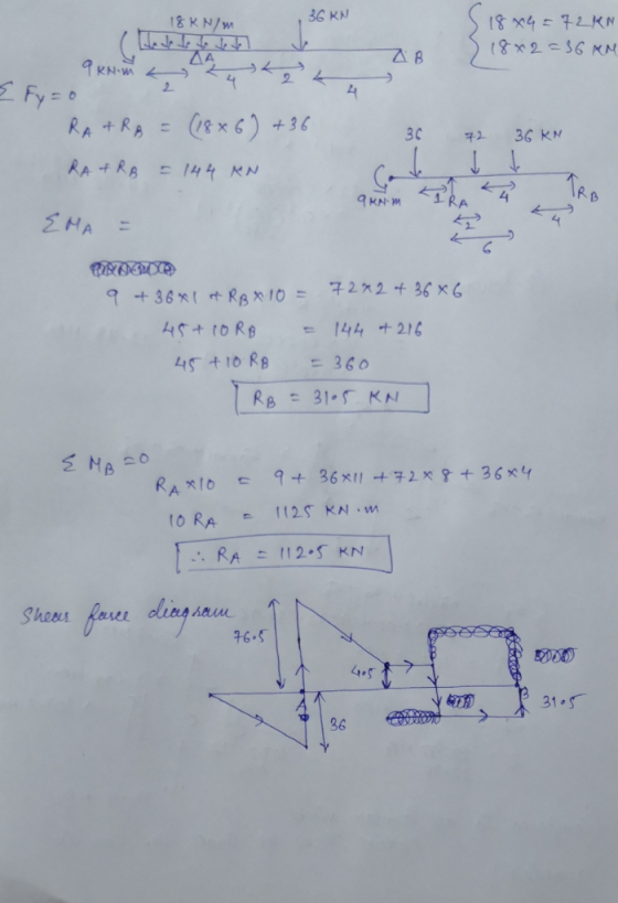
Example Draw complete shear and moment diagrams for the beam shown in Fig y 36 kN...
For the beam shown in Fig. 9.3, draw the shear force and bending moment diagrams. Use...
 For the beam shown in Fig. 9.3, draw the shear force and bending moment diagrams. Use the area method that relies on the relationships between loading and shear force and between shear force and bending moment. Indicate the slope of the shear force diagram at locations A, B, C, and D using the load information in Fig. 9.3. Indicate the slope of the bending moment diagram at the same four locations using information from the shear force diagram. | 6...
Draw the shear and moment diagrams for the cantilever beam in Fig. 6-15a. 2 kN 1.5...
 Draw the shear and moment diagrams for the cantilever beam in Fig. 6-15a. 2 kN 1.5 kN/m 2 m 2 m
Question 1: (20 Points) For the beam and loading shown: a- Draw shear and moment diagrams. b- Write equations of shear and moment for all segments of the beam from 20 kN 0 kN 8 kN/m x =-4 to x = 8, U...
 Question 1: (20 Points) For the beam and loading shown: a- Draw shear and moment diagrams. b- Write equations of shear and moment for all segments of the beam from 20 kN 0 kN 8 kN/m x =-4 to x = 8, Use x-y axes as shown. Do not change x-y coordinates. Answers: M56 kN-mx4.09 kN-m
Question 1: (20 Points) For the beam and loading shown: a- Draw shear and moment diagrams. b- Write equations of shear and moment for...
Question 1: (20 Points) For the beam and loading shown: a- Draw shear and moment diagrams. b- Write equations of shear and moment for all segments of the beam from 20 kN 0 kN 8 kN/m x =-4 to x = 8, Use x-y axes as shown. Do not change x-y coordinates. Answers: M56 kN-mx4.09 kN-m
Question 1: (20 Points) For the beam and loading shown: a- Draw shear and moment diagrams. b- Write equations of shear and moment for...
For the beam shown, draw the shear and bending moment diagrams and determine the magnitude and...
 For the beam shown, draw the shear and bending moment diagrams and determine the magnitude and location of the maximum absolute values of bending moment knowing that a) M 0, b) M 12 kNm.(7, 30) 20 kN/m С В М A 2m- 2 m
4. For the beam and loading shown, draw the shear force and bending moment diagrams and...
 4. For the beam and loading shown, draw the shear force and bending moment diagrams and determine the maximum bending and shear force and their locations. 20 KN 40 KN B D 250 mm |--2.5 m- 3m-4-2 m 80 mm 5. For the beam and loading shown, draw the shear force and bending moment diagrams and determine the maximum bending and shear force and their locations. 50 KN
draw the shear and moment diagrams for the beam Example 1 Draw the shear and moment...
 draw the shear and moment diagrams for the beam
Example 1 Draw the shear and moment diagrams for the beam. 300 N/m
draw the shear and moment diagrams for the beam
Example 1 Draw the shear and moment diagrams for the beam. 300 N/m
For the beam and loading shown, draw the shear and bending moment diagrams, and determine the...
 For the beam and loading shown, draw the shear and bending moment diagrams, and determine the magnitude and location of the maximum shear and bending moment. 2 kN/m AC D 6 NT 3kN/m lm-- 1.2 m 0.6 m
Draw the shear force and bending-moment diagrams for the simply supported beam shown. Label each diagram...
 Draw the shear force and bending-moment diagrams for the simply
supported beam shown. Label each diagram with the corresponding
values
1. Draw the shear force and bending-moment diagrams for the simply supported beam shown. Label each diagram with the corresponding values. 3 Pe= 30 KN 4 m - m 3 m - C -40 kN - m
Draw the shear force and bending-moment diagrams for the simply
supported beam shown. Label each diagram with the corresponding
values
1. Draw the shear force and bending-moment diagrams for the simply supported beam shown. Label each diagram with the corresponding values. 3 Pe= 30 KN 4 m - m 3 m - C -40 kN - m
Draw the shear and bending moment diagrams and the qualitative deflected shape for the beam shown in Fig. 5.10(a)
 Draw the shear and bending moment diagrams and the qualitative deflected shape for the beam shown in Fig. 5.10(a)
Draw the shear and moment diagrams for the beam and loading shown. Determination of the shear...
 Draw the shear and moment diagrams for the beam and loading
shown. Determination of the shear and moment as functions of
position is not required. Take P = 3.75 lb and Q
= 8.5 lb.
Please explain step by step your solution
Thank you
y 19 P 4 lb с A EX E AB CD 5 in. 5 in. 5 in. 5 in.
Draw the shear and moment diagrams for the beam and loading
shown. Determination of the shear and moment as functions of
position is not required. Take P = 3.75 lb and Q
= 8.5 lb.
Please explain step by step your solution
Thank you
y 19 P 4 lb с A EX E AB CD 5 in. 5 in. 5 in. 5 in.
 For the beam shown in Fig. 9.3, draw the shear force and bending moment diagrams. Use the area method that relies on the relationships between loading and shear force and between shear force and bending moment. Indicate the slope of the shear force diagram at locations A, B, C, and D using the load information in Fig. 9.3. Indicate the slope of the bending moment diagram at the same four locations using information from the shear force diagram. | 6...
 Draw the shear and moment diagrams for the cantilever beam in Fig. 6-15a. 2 kN 1.5 kN/m 2 m 2 m
 Question 1: (20 Points) For the beam and loading shown: a- Draw shear and moment diagrams. b- Write equations of shear and moment for all segments of the beam from 20 kN 0 kN 8 kN/m x =-4 to x = 8, Use x-y axes as shown. Do not change x-y coordinates. Answers: M56 kN-mx4.09 kN-m
Question 1: (20 Points) For the beam and loading shown: a- Draw shear and moment diagrams. b- Write equations of shear and moment for...
Question 1: (20 Points) For the beam and loading shown: a- Draw shear and moment diagrams. b- Write equations of shear and moment for all segments of the beam from 20 kN 0 kN 8 kN/m x =-4 to x = 8, Use x-y axes as shown. Do not change x-y coordinates. Answers: M56 kN-mx4.09 kN-m
Question 1: (20 Points) For the beam and loading shown: a- Draw shear and moment diagrams. b- Write equations of shear and moment for...
 For the beam shown, draw the shear and bending moment diagrams and determine the magnitude and location of the maximum absolute values of bending moment knowing that a) M 0, b) M 12 kNm.(7, 30) 20 kN/m С В М A 2m- 2 m
 4. For the beam and loading shown, draw the shear force and bending moment diagrams and determine the maximum bending and shear force and their locations. 20 KN 40 KN B D 250 mm |--2.5 m- 3m-4-2 m 80 mm 5. For the beam and loading shown, draw the shear force and bending moment diagrams and determine the maximum bending and shear force and their locations. 50 KN
 draw the shear and moment diagrams for the beam
Example 1 Draw the shear and moment diagrams for the beam. 300 N/m
draw the shear and moment diagrams for the beam
Example 1 Draw the shear and moment diagrams for the beam. 300 N/m
 For the beam and loading shown, draw the shear and bending moment diagrams, and determine the magnitude and location of the maximum shear and bending moment. 2 kN/m AC D 6 NT 3kN/m lm-- 1.2 m 0.6 m
 Draw the shear force and bending-moment diagrams for the simply
supported beam shown. Label each diagram with the corresponding
values
1. Draw the shear force and bending-moment diagrams for the simply supported beam shown. Label each diagram with the corresponding values. 3 Pe= 30 KN 4 m - m 3 m - C -40 kN - m
Draw the shear force and bending-moment diagrams for the simply
supported beam shown. Label each diagram with the corresponding
values
1. Draw the shear force and bending-moment diagrams for the simply supported beam shown. Label each diagram with the corresponding values. 3 Pe= 30 KN 4 m - m 3 m - C -40 kN - m
 Draw the shear and moment diagrams for the beam and loading
shown. Determination of the shear and moment as functions of
position is not required. Take P = 3.75 lb and Q
= 8.5 lb.
Please explain step by step your solution
Thank you
y 19 P 4 lb с A EX E AB CD 5 in. 5 in. 5 in. 5 in.
Draw the shear and moment diagrams for the beam and loading
shown. Determination of the shear and moment as functions of
position is not required. Take P = 3.75 lb and Q
= 8.5 lb.
Please explain step by step your solution
Thank you
y 19 P 4 lb с A EX E AB CD 5 in. 5 in. 5 in. 5 in.
Most questions answered within 3 hours.
-
A simple random sample of size n=64 is obtained from a
population with a mean of...
asked 5 minutes ago -
(2 dimensions, 1 object, 2 accelerations)
1) A projectile is thrown with a wind. The wind...
asked 52 minutes ago -
Brian makes $34,100 per year. How much can Brian expect to
contribute to FICA taxes in...
asked 1 hour ago -
To buy a new house you must borrow $155,000. To do this you take
out a...
asked 1 hour ago -
Spacely Sprockets is evaluating the construction of a new plant
on land the company purchased for...
asked 2 hours ago -
1. Consider a linear regression model of y on K regressors and
an intercept.
(i) Describe...
asked 2 hours ago -
Enter a balanced equation for the reaction between hydrochloric
acid and sodium sulfite.
Express your answer...
asked 2 hours ago -
Give a regular expression describing the language
{x | x ∈ Σ* and x does not...
asked 2 hours ago -
Masses of 1.0 kg, 2.0 kg, and 3.0 kg are each separately subject
to a net...
asked 2 hours ago -
The mode of philosophical argumentation and thought. How do
philosophers think and write? What is important...
asked 3 hours ago -
At the beginning of the unit, you were asked whether you thought
it was appropriate or...
asked 3 hours ago -
Calculate the grams of carbon in 9.32 x 10+23 molecules of
benzene (C6H6).
asked 3 hours ago