DC Motor Position Control System
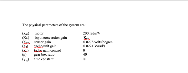
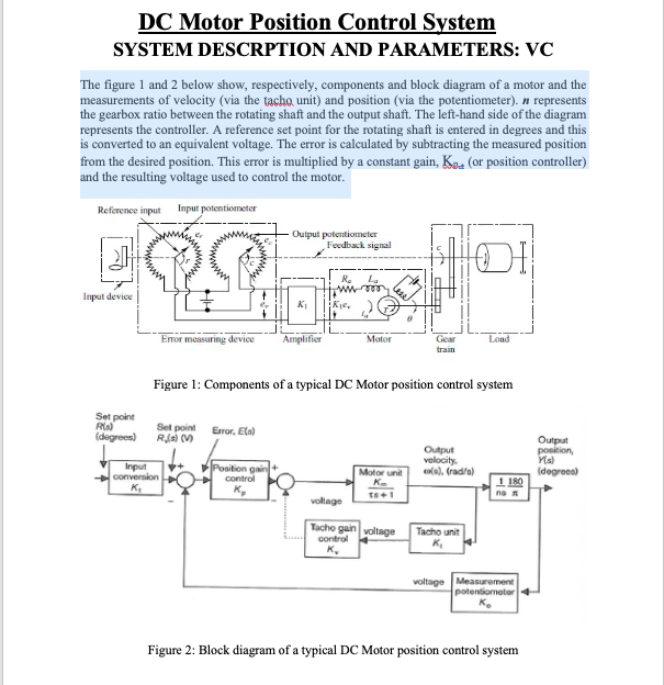
The figure 1 and 2 below show, respectively, components and block diagram of a motor and the measurements of velocity (via the tacho unit) and position (via the potentiometer). n represents the gearbox ratio between the rotating shaft and the output shaft. The left-hand side of the diagram represents the controller. A reference set point for the rotating shaft is entered in degrees and this is converted to an equivalent voltage. The error is calculated by subtracting the measured position from the desired position. This error is multiplied by a constant gain, Kp , (or position controller) and the resulting voltage used to control the motor.
![]() Screen Shot 2020-05-08 at 2.23.59 AM.png
Screen Shot 2020-05-08 at 2.23.59 AM.png
![]() Screen Shot 2020-05-08 at 2.24.18 AM.png
Screen Shot 2020-05-08 at 2.24.18 AM.png
![]() Screen Shot 2020-05-08 at 2.23.53 AM.png
Screen Shot 2020-05-08 at 2.23.53 AM.png
Homework Answers
Request Answer!
We need at least 7 more requests to produce the answer.
3 / 10 have requested this problem solution
The more requests, the faster the answer.
DC Motor Position Control System
 The figure 1 and 2 below show, respectively, components and block diagram of a motor and the measurements of velocity (via the tacho unit) and position (via the potentiometer). n represents the gearbox ratio between the rotating shaft and the output shaft. The left-hand side of the diagram represents the controller. A reference set point for the rotating shaft is entered in degrees and this is converted to an equivalent voltage. The error is calculated by subtracting the measured position from the...
control system System Description: The figure 1 and 2 below show, respectively, components and block diagram...
 control system
System Description: The figure 1 and 2 below show, respectively, components and block diagram of a motor and the measurements of velocity (via the tacho unit) and position (via the potentiometer). n represents the gearbox ratio between the rotating shaft and the output shaft. The left-hand side of the diagram represents the controller. A reference set point for the rotating shaft is entered in degrees and this is equivalent voltage. The error is calculated by subtracting the measured...
control system
System Description: The figure 1 and 2 below show, respectively, components and block diagram of a motor and the measurements of velocity (via the tacho unit) and position (via the potentiometer). n represents the gearbox ratio between the rotating shaft and the output shaft. The left-hand side of the diagram represents the controller. A reference set point for the rotating shaft is entered in degrees and this is equivalent voltage. The error is calculated by subtracting the measured...
A simple but practical feedback control system is shown below. It is a positioning system or posi...
 please solve this problem with detail description.
A simple but practical feedback control system is shown below. It is a positioning system or position servo for a large video satellite antenna modeled as a mass having a large moment of inertia, J. An output potentiometer measures the output shaft position, converting the position to a proportional voltage according to vo-Kye. where, e is the output shaft angle in radians and vo is the output potentiometer voltage; Kp is the constant...
please solve this problem with detail description.
A simple but practical feedback control system is shown below. It is a positioning system or position servo for a large video satellite antenna modeled as a mass having a large moment of inertia, J. An output potentiometer measures the output shaft position, converting the position to a proportional voltage according to vo-Kye. where, e is the output shaft angle in radians and vo is the output potentiometer voltage; Kp is the constant...
Motor Position Control with Torque Disturbance The following diagram models a motor position control system with...
 Motor Position Control with
Torque Disturbance
The following diagram models a
motor position control system with torque disturbance. The motor
transfer function from torque to position (when connected to a
voltage source) is G(s) = 1/s(0.1s + 1).
Problem 5-1: Motor Position Control with Torque Disturbance The following diagram models a motor position control system with torque disturbance. The motor transfer function from torque to position (when connected to a voltage source) is s(0.1s +1) The gain K in this...
Motor Position Control with
Torque Disturbance
The following diagram models a
motor position control system with torque disturbance. The motor
transfer function from torque to position (when connected to a
voltage source) is G(s) = 1/s(0.1s + 1).
Problem 5-1: Motor Position Control with Torque Disturbance The following diagram models a motor position control system with torque disturbance. The motor transfer function from torque to position (when connected to a voltage source) is s(0.1s +1) The gain K in this...
Control Lab
 Obtain the Simulink diagram of position control system shown in figure 1 and run the simulation. Assume the following numerical values for system constants:r = angular displacement of reference input shaft, radiansc = angular displacement of the output shaft, radiansθ = angular displacement of the motor shaft, radiansk1 = gain of the potentiometer error detector = 24/π volt/radkp = amplifier gain = 10 volt/voltea = applied armature voltage, volteb = back emf, voltRa = armature resistance, ohmsLa = armature winding...
Problem 51: (25 points) Figure 5 is an example of a feedback control system that is designed to r...
 Problem 51: (25 points) Figure 5 is an example of a feedback control system that is designed to regulate the angular position θ(t) of a motor shaft to a desired value θr(t). The signal e(t) represents the error between the measured shaft angle θ(t) and the desired shaft angle θ (t). The Laplace transforms ofa,(t), θ(t), and e(t) are denoted as ΘR(s), θ(s), and E(s), respectively. The control gains Ki and K2 are chosen by the control engineer to achieve...
summarizr the followung info and write them in your own words and break them into different...
summarizr the followung info and write them in your own words and break them into different key points. 6.5 Metering Chamber: 6.5.1 The minimum size of the metering box is governed by the metering area required to obtain a representative test area for the specimen (see 7.2) and for maintenance of reasonable test accuracy. For example, for specimens incorporating air spaces or stud spaces, the metering area shall span an integral number of spaces (see 5.5). The depth of...
summatize the following info and break them into differeng key points. write them in yojr own...
 summatize the following info and break them into differeng key points. write them in yojr own words
apartus
6.1 Introduction—The design of a successful hot box appa- ratus is influenced by many factors. Before beginning the design of an apparatus meeting this standard, the designer shall review the discussion on the limitations and accuracy, Section 13, discussions of the energy flows in a hot box, Annex A2, the metering box wall loss flow, Annex A3, and flanking loss, Annex...
summatize the following info and break them into differeng key points. write them in yojr own words
apartus
6.1 Introduction—The design of a successful hot box appa- ratus is influenced by many factors. Before beginning the design of an apparatus meeting this standard, the designer shall review the discussion on the limitations and accuracy, Section 13, discussions of the energy flows in a hot box, Annex A2, the metering box wall loss flow, Annex A3, and flanking loss, Annex...
 control system
System Description: The figure 1 and 2 below show, respectively, components and block diagram of a motor and the measurements of velocity (via the tacho unit) and position (via the potentiometer). n represents the gearbox ratio between the rotating shaft and the output shaft. The left-hand side of the diagram represents the controller. A reference set point for the rotating shaft is entered in degrees and this is equivalent voltage. The error is calculated by subtracting the measured...
control system
System Description: The figure 1 and 2 below show, respectively, components and block diagram of a motor and the measurements of velocity (via the tacho unit) and position (via the potentiometer). n represents the gearbox ratio between the rotating shaft and the output shaft. The left-hand side of the diagram represents the controller. A reference set point for the rotating shaft is entered in degrees and this is equivalent voltage. The error is calculated by subtracting the measured...
 please solve this problem with detail description.
A simple but practical feedback control system is shown below. It is a positioning system or position servo for a large video satellite antenna modeled as a mass having a large moment of inertia, J. An output potentiometer measures the output shaft position, converting the position to a proportional voltage according to vo-Kye. where, e is the output shaft angle in radians and vo is the output potentiometer voltage; Kp is the constant...
please solve this problem with detail description.
A simple but practical feedback control system is shown below. It is a positioning system or position servo for a large video satellite antenna modeled as a mass having a large moment of inertia, J. An output potentiometer measures the output shaft position, converting the position to a proportional voltage according to vo-Kye. where, e is the output shaft angle in radians and vo is the output potentiometer voltage; Kp is the constant...
 Motor Position Control with
Torque Disturbance
The following diagram models a
motor position control system with torque disturbance. The motor
transfer function from torque to position (when connected to a
voltage source) is G(s) = 1/s(0.1s + 1).
Problem 5-1: Motor Position Control with Torque Disturbance The following diagram models a motor position control system with torque disturbance. The motor transfer function from torque to position (when connected to a voltage source) is s(0.1s +1) The gain K in this...
Motor Position Control with
Torque Disturbance
The following diagram models a
motor position control system with torque disturbance. The motor
transfer function from torque to position (when connected to a
voltage source) is G(s) = 1/s(0.1s + 1).
Problem 5-1: Motor Position Control with Torque Disturbance The following diagram models a motor position control system with torque disturbance. The motor transfer function from torque to position (when connected to a voltage source) is s(0.1s +1) The gain K in this...
 Problem 51: (25 points) Figure 5 is an example of a feedback control system that is designed to regulate the angular position θ(t) of a motor shaft to a desired value θr(t). The signal e(t) represents the error between the measured shaft angle θ(t) and the desired shaft angle θ (t). The Laplace transforms ofa,(t), θ(t), and e(t) are denoted as ΘR(s), θ(s), and E(s), respectively. The control gains Ki and K2 are chosen by the control engineer to achieve...
 summatize the following info and break them into differeng key points. write them in yojr own words
apartus
6.1 Introduction—The design of a successful hot box appa- ratus is influenced by many factors. Before beginning the design of an apparatus meeting this standard, the designer shall review the discussion on the limitations and accuracy, Section 13, discussions of the energy flows in a hot box, Annex A2, the metering box wall loss flow, Annex A3, and flanking loss, Annex...
summatize the following info and break them into differeng key points. write them in yojr own words
apartus
6.1 Introduction—The design of a successful hot box appa- ratus is influenced by many factors. Before beginning the design of an apparatus meeting this standard, the designer shall review the discussion on the limitations and accuracy, Section 13, discussions of the energy flows in a hot box, Annex A2, the metering box wall loss flow, Annex A3, and flanking loss, Annex...
Most questions answered within 3 hours.
-
Calculate the number density of argon gas at a temperature of
24C and a pressure of...
asked 28 minutes ago -
Alternative
Classification
How to Estimate
Probabilities from Data? ( For continuous Attributes)
And How to generate...
asked 31 minutes ago -
An explosion breaks a 20.0-kg object into three parts. The
object is initially moving at a...
asked 1 hour ago -
Calculate the approximate number of residues of Rubisco, which
is involved in carbon fixation in plants,...
asked 2 hours ago -
Other decisions about scientific claims can have a much broader
impact.ENERGYarrow-10x10.png, environment, health, security - all...
asked 3 hours ago -
I need to write a research paper and work cited about this
topic: The United States...
asked 3 hours ago -
Hello! I was wondering if I could have some help?
If the vapor pressure of carvone...
asked 4 hours ago -
An economist wants to estimate the mean per capita income (in
thousands of dollars) for a...
asked 4 hours ago -
What would be the input/output characteristic of a circuit
obtained by putting two of your 2's-complementers...
asked 4 hours ago -
In Drosophila, the transition from the syncytial blastoderm
stage to the cellular blastoderm stage is a...
asked 4 hours ago -
Project management question:
Name 3 different types of resources (hint: humans are one
type)
asked 5 hours ago -
Consider the following reaction: C 2H 2( g) + 2H 2( g) C 2H 6(
g)...
asked 5 hours ago