
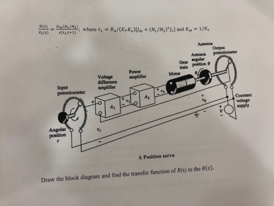
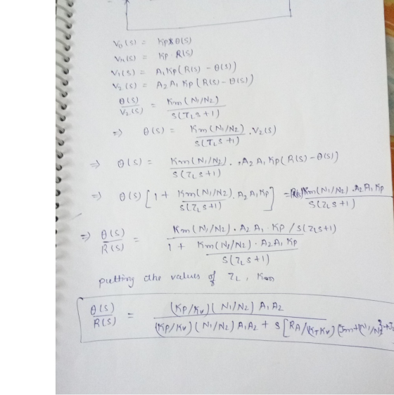
½(s) s(TLS+1) Output Antenna potentiometer Gear angular train position θ Power difference amplifier amplifier Motor Input potentiometer Vo voltage supply Angular position A Position servo Draw the block diagram and find the transfer function of R(s) to the θ(s).
Homework Answers
Add Answer to:
A simple but practical feedback control system is shown below. It is a positioning system or posi...
Control Lab
 Obtain the Simulink diagram of position control system shown in figure 1 and run the simulation. Assume the following numerical values for system constants:r = angular displacement of reference input shaft, radiansc = angular displacement of the output shaft, radiansθ = angular displacement of the motor shaft, radiansk1 = gain of the potentiometer error detector = 24/π volt/radkp = amplifier gain = 10 volt/voltea = applied armature voltage, volteb = back emf, voltRa = armature resistance, ohmsLa = armature winding...
D.C. motor is shown below, where the inductance L and the resistance R model the armature circuit. The voltage Vbrepresents the back-emf which is proportional to dθ/dt via Kf. The torque T generated b...
 D.C. motor is shown below, where the inductance
L and the resistance R model the
armature circuit. The voltage
Vbrepresents the back-emf
which is proportional to dθ/dt via
Kf. The torque T
generated by the motor is proportional to the
i via a constant
Kt. In this application, let the
constants Kt =
Kf. The inertia
Jrepresents the combined inertia of the motor and
load. The viscous friction acting on the output shaft is
b. Attached to the shaft is...
D.C. motor is shown below, where the inductance
L and the resistance R model the
armature circuit. The voltage
Vbrepresents the back-emf
which is proportional to dθ/dt via
Kf. The torque T
generated by the motor is proportional to the
i via a constant
Kt. In this application, let the
constants Kt =
Kf. The inertia
Jrepresents the combined inertia of the motor and
load. The viscous friction acting on the output shaft is
b. Attached to the shaft is...
control system System Description: The figure 1 and 2 below show, respectively, components and block diagram...
 control system
System Description: The figure 1 and 2 below show, respectively, components and block diagram of a motor and the measurements of velocity (via the tacho unit) and position (via the potentiometer). n represents the gearbox ratio between the rotating shaft and the output shaft. The left-hand side of the diagram represents the controller. A reference set point for the rotating shaft is entered in degrees and this is equivalent voltage. The error is calculated by subtracting the measured...
control system
System Description: The figure 1 and 2 below show, respectively, components and block diagram of a motor and the measurements of velocity (via the tacho unit) and position (via the potentiometer). n represents the gearbox ratio between the rotating shaft and the output shaft. The left-hand side of the diagram represents the controller. A reference set point for the rotating shaft is entered in degrees and this is equivalent voltage. The error is calculated by subtracting the measured...
Q 1- 08 Pts) Figure below is a diagram of a DC motor connected in parnllel to a current source i,...
 Q 1- 08 Pts) Figure below is a diagram of a DC motor connected in parnllel to a current source i,. The torque and back-EMF constants of the motor are Ko K respectively, the motor resistance is R, also modeled as connected in parallel, the motor inertia is 1- (not shown), and the motor inductance is negligible. The motor load is an inertia J with compliance (stiffness) K and viscous friction coefficient b, and it is attached a gear pair...
D.C. motor is shown below, where the inductance L and the resistance R model the armature...
 D.C. motor is shown below, where the inductance
L and the resistance R model the
armature circuit. The voltage
Vbrepresents the back-emf
which is proportional to dθ/dt via
Kf. The torque T
generated by the motor is proportional to the
i via a constant
Kt. In this application, let the
constants Kt =
Kf. The inertia J
represents the combined inertia of the motor and load. The viscous
friction acting on the output shaft is b. Attached
to the shaft...
D.C. motor is shown below, where the inductance
L and the resistance R model the
armature circuit. The voltage
Vbrepresents the back-emf
which is proportional to dθ/dt via
Kf. The torque T
generated by the motor is proportional to the
i via a constant
Kt. In this application, let the
constants Kt =
Kf. The inertia J
represents the combined inertia of the motor and load. The viscous
friction acting on the output shaft is b. Attached
to the shaft...
Q6 (a) A double stage compound gear system as shown in Figure Q6(a) has a meshing...
 Q6 (a) A double stage compound gear system as shown in Figure Q6(a) has a meshing efficiency, n of 0.8 individually. Moment inertia of each shaft A, shaft B to C and shaft Dare 5 kg/m 30 kg/m' and 20 kg/m' respectively. Calculate the required motor power at input shaft to overcome the equivalent inertia given angular acceleration of motor is 10 rad/s? (10 marks) Output Shaft Gear C 80 Teeth Gear D 200 Teeth Gear B 200 Teeth Gear...
3.3 Consider the positional servomechanism shown in Fig. P3.3. Assume that the input to the system...
 3.3 Consider the positional servomechanism shown in Fig. P3.3. Assume that the input to the system is reference shaft position ®, and the system output is the load shaft position 0. Draw a block diagram of the system indicating the transfer function of each block. Simplify the block diagram to obtain (s)/e (s). The parameters of the system are given below. Sensitivity of error detector K = 10 volts/rad Amplifier gain K = 50 volts/volt Motor field resistance R,= 100...
In the gear train shown below, the pinion 2 is the driver, and gear 5 is...
 In the gear train shown below, the pinion 2 is the driver, and gear 5 is the output gear. All gears are spur gears has a module of 2.5mm and pressure angle of 200. The number of gear teeth are: N2 - 14, N3 - 84, N4 - 14, N5 - 70 teeth. The gear set transmits the power of 1.5KW at a constant angular velocity of XX rev/min. Where XX is the last two digits of your University ID...
01- (08 Pts) Figure below is a diagram of a DC motor connected in parallel to...
 01- (08 Pts) Figure below is a diagram of a DC motor connected in parallel to a current source is the torque and back-EMF constants of the motor are K. K respectively, the motor resistance is R, also modeled as connected in parallel, the motor inertia is I. (not shown), and the motor inductance is negligible. The motor load is an inertia compliance (stiffness) K and viscous friction coefficient b, and it is attached to the motor via a gear...
(30 pts) A D.C. motor is shown below, where the inductance L and the resistance R model the armat...
 (30 pts) A D.C. motor is shown below, where the inductance L and the resistance R model the armature circuit. The voltage Vb represents the back-emf which is proportional to dθ/dt via K. The torque T generated by the motor is proportional to the i via a constant K. The inertia J represents the combined inertia of the motor and load. The viscous friction acting on the output shaft is B 1. pur voltaop a. A. (10 pts) Find the...
 D.C. motor is shown below, where the inductance
L and the resistance R model the
armature circuit. The voltage
Vbrepresents the back-emf
which is proportional to dθ/dt via
Kf. The torque T
generated by the motor is proportional to the
i via a constant
Kt. In this application, let the
constants Kt =
Kf. The inertia
Jrepresents the combined inertia of the motor and
load. The viscous friction acting on the output shaft is
b. Attached to the shaft is...
D.C. motor is shown below, where the inductance
L and the resistance R model the
armature circuit. The voltage
Vbrepresents the back-emf
which is proportional to dθ/dt via
Kf. The torque T
generated by the motor is proportional to the
i via a constant
Kt. In this application, let the
constants Kt =
Kf. The inertia
Jrepresents the combined inertia of the motor and
load. The viscous friction acting on the output shaft is
b. Attached to the shaft is...
 control system
System Description: The figure 1 and 2 below show, respectively, components and block diagram of a motor and the measurements of velocity (via the tacho unit) and position (via the potentiometer). n represents the gearbox ratio between the rotating shaft and the output shaft. The left-hand side of the diagram represents the controller. A reference set point for the rotating shaft is entered in degrees and this is equivalent voltage. The error is calculated by subtracting the measured...
control system
System Description: The figure 1 and 2 below show, respectively, components and block diagram of a motor and the measurements of velocity (via the tacho unit) and position (via the potentiometer). n represents the gearbox ratio between the rotating shaft and the output shaft. The left-hand side of the diagram represents the controller. A reference set point for the rotating shaft is entered in degrees and this is equivalent voltage. The error is calculated by subtracting the measured...
 Q 1- 08 Pts) Figure below is a diagram of a DC motor connected in parnllel to a current source i,. The torque and back-EMF constants of the motor are Ko K respectively, the motor resistance is R, also modeled as connected in parallel, the motor inertia is 1- (not shown), and the motor inductance is negligible. The motor load is an inertia J with compliance (stiffness) K and viscous friction coefficient b, and it is attached a gear pair...
 D.C. motor is shown below, where the inductance
L and the resistance R model the
armature circuit. The voltage
Vbrepresents the back-emf
which is proportional to dθ/dt via
Kf. The torque T
generated by the motor is proportional to the
i via a constant
Kt. In this application, let the
constants Kt =
Kf. The inertia J
represents the combined inertia of the motor and load. The viscous
friction acting on the output shaft is b. Attached
to the shaft...
D.C. motor is shown below, where the inductance
L and the resistance R model the
armature circuit. The voltage
Vbrepresents the back-emf
which is proportional to dθ/dt via
Kf. The torque T
generated by the motor is proportional to the
i via a constant
Kt. In this application, let the
constants Kt =
Kf. The inertia J
represents the combined inertia of the motor and load. The viscous
friction acting on the output shaft is b. Attached
to the shaft...
 Q6 (a) A double stage compound gear system as shown in Figure Q6(a) has a meshing efficiency, n of 0.8 individually. Moment inertia of each shaft A, shaft B to C and shaft Dare 5 kg/m 30 kg/m' and 20 kg/m' respectively. Calculate the required motor power at input shaft to overcome the equivalent inertia given angular acceleration of motor is 10 rad/s? (10 marks) Output Shaft Gear C 80 Teeth Gear D 200 Teeth Gear B 200 Teeth Gear...
 3.3 Consider the positional servomechanism shown in Fig. P3.3. Assume that the input to the system is reference shaft position ®, and the system output is the load shaft position 0. Draw a block diagram of the system indicating the transfer function of each block. Simplify the block diagram to obtain (s)/e (s). The parameters of the system are given below. Sensitivity of error detector K = 10 volts/rad Amplifier gain K = 50 volts/volt Motor field resistance R,= 100...
 In the gear train shown below, the pinion 2 is the driver, and gear 5 is the output gear. All gears are spur gears has a module of 2.5mm and pressure angle of 200. The number of gear teeth are: N2 - 14, N3 - 84, N4 - 14, N5 - 70 teeth. The gear set transmits the power of 1.5KW at a constant angular velocity of XX rev/min. Where XX is the last two digits of your University ID...
 01- (08 Pts) Figure below is a diagram of a DC motor connected in parallel to a current source is the torque and back-EMF constants of the motor are K. K respectively, the motor resistance is R, also modeled as connected in parallel, the motor inertia is I. (not shown), and the motor inductance is negligible. The motor load is an inertia compliance (stiffness) K and viscous friction coefficient b, and it is attached to the motor via a gear...
 (30 pts) A D.C. motor is shown below, where the inductance L and the resistance R model the armature circuit. The voltage Vb represents the back-emf which is proportional to dθ/dt via K. The torque T generated by the motor is proportional to the i via a constant K. The inertia J represents the combined inertia of the motor and load. The viscous friction acting on the output shaft is B 1. pur voltaop a. A. (10 pts) Find the...
Most questions answered within 3 hours.
-
For Dijkstra’s shortest path algorithm:
a. Give the Big-O time for Dijkstra’s shortest path algorithm
and...
asked 1 minute from now -
Phosphorus violates the 'octet rule' in biological molecules,
forming more covalent bonds than expected based on...
asked 1 minute ago -
A 1.3 eV electron has a 10-4 probability of tunneling
through a 2.4 eV potential barrier....
asked 20 minutes ago -
What is the one ingredient that is common to being successful
with all stakeholders?
profit
trust...
asked 18 minutes ago -
Write an assembly language 32 bit program that reads in lines of
text by a .txt...
asked 21 minutes ago -
what is the density ( in g/L) of hydrogen gas at 29 degrees C and a...
asked 30 minutes ago -
5-6. You are considering three investment alternatives for some
spare cash: Old Reliable Corporation stock (A1),...
asked 21 minutes ago -
Problem 16-02
Receivables Investment
Medwig Corporation has a DSO of 45 days. The company averages
$7,250...
asked 37 minutes ago -
Mr. Brown hired Lowe's Maintenance Services Limited to repair
and paint the exterior wall of his...
asked 37 minutes ago -
When might an index slow down the overall performance of the
database? Choose the best answer....
asked 42 minutes ago -
Due to a recession, expected inflation this year is only 2.25%.
However, the inflation rate in...
asked 44 minutes ago -
Write four functions: (IN PYTHON 3)
1) bound(l) - given a list of integers l, compute...
asked 46 minutes ago