
Homework Answers


Hope this helps
Add Answer to:
(30 pts) A D.C. motor is shown below, where the inductance L and the resistance R model the armat...
D.C. motor is shown below, where the inductance L and the resistance R model the armature...
 D.C. motor is shown below, where the inductance
L and the resistance R model the
armature circuit. The voltage
Vbrepresents the back-emf
which is proportional to dθ/dt via
Kf. The torque T
generated by the motor is proportional to the
i via a constant
Kt. In this application, let the
constants Kt =
Kf. The inertia J
represents the combined inertia of the motor and load. The viscous
friction acting on the output shaft is b. Attached
to the shaft...
D.C. motor is shown below, where the inductance
L and the resistance R model the
armature circuit. The voltage
Vbrepresents the back-emf
which is proportional to dθ/dt via
Kf. The torque T
generated by the motor is proportional to the
i via a constant
Kt. In this application, let the
constants Kt =
Kf. The inertia J
represents the combined inertia of the motor and load. The viscous
friction acting on the output shaft is b. Attached
to the shaft...
D.C. motor is shown below, where the inductance L and the resistance R model the armature circuit. The voltage Vbrepresents the back-emf which is proportional to dθ/dt via Kf. The torque T generated b...
 D.C. motor is shown below, where the inductance
L and the resistance R model the
armature circuit. The voltage
Vbrepresents the back-emf
which is proportional to dθ/dt via
Kf. The torque T
generated by the motor is proportional to the
i via a constant
Kt. In this application, let the
constants Kt =
Kf. The inertia
Jrepresents the combined inertia of the motor and
load. The viscous friction acting on the output shaft is
b. Attached to the shaft is...
D.C. motor is shown below, where the inductance
L and the resistance R model the
armature circuit. The voltage
Vbrepresents the back-emf
which is proportional to dθ/dt via
Kf. The torque T
generated by the motor is proportional to the
i via a constant
Kt. In this application, let the
constants Kt =
Kf. The inertia
Jrepresents the combined inertia of the motor and
load. The viscous friction acting on the output shaft is
b. Attached to the shaft is...
Q 1- 08 Pts) Figure below is a diagram of a DC motor connected in parnllel to a current source i,...
 Q 1- 08 Pts) Figure below is a diagram of a DC motor connected in parnllel to a current source i,. The torque and back-EMF constants of the motor are Ko K respectively, the motor resistance is R, also modeled as connected in parallel, the motor inertia is 1- (not shown), and the motor inductance is negligible. The motor load is an inertia J with compliance (stiffness) K and viscous friction coefficient b, and it is attached a gear pair...
01- (08 Pts) Figure below is a diagram of a DC motor connected in parallel to...
 01- (08 Pts) Figure below is a diagram of a DC motor connected in parallel to a current source is the torque and back-EMF constants of the motor are K. K respectively, the motor resistance is R, also modeled as connected in parallel, the motor inertia is I. (not shown), and the motor inductance is negligible. The motor load is an inertia compliance (stiffness) K and viscous friction coefficient b, and it is attached to the motor via a gear...
Problem-5 (20 pts): Consider the DC servo motor shown in Figure-5. Assume that the input of the s...
 Problem-5 (20 pts): Consider the DC servo motor shown in Figure-5. Assume that the input of the system is the applied armature voltage ea and the output is the load shaft position θ2. Assume also the following numerical values for the components: Ra-) Armature winding resistance = 0.2Ω La → Armature winding inductance = 0.1 mH Kb-) Back emf constant 0.05 Vs/rad K > Motor torque constant 0.06 Nm/A Jr Moment of inertia of the rotor of the motor =...
Figure Q1(b) shows the simplified diagram of the armature controlled D.C. b) servomotors used in instruments...
 Figure Q1(b) shows the simplified diagram of the armature controlled D.C. b) servomotors used in instruments and employed a fixed permane nt magnet field. The control signal is app lied to the amature terminals. The inductance of armature winding is negligible. Obtain the transfer function of the servo mot or (assume K, K, and K, are constant) i) (10marks) Derive a state spa ce model for the servomotor (armature resistance is 0.2) (5marks) i) La Fixed field (if) Ra ww00...
2. (20 points) A field controlled DC motor model is given below where eaſt) is an...
 2. (20 points) A field controlled DC motor model is given below where eaſt) is an applied input voltage, ia(t) is the armature current, Ra and La are the armature resistance and inductance, respectively, e(t) is a back (or counter) emf (electro-motive force) le (t) = K w here K is a motor (torque) constant, t(t) is the torque generated by the motor, w(t) is the angular velocity, 0(t) is the angular position, J represents the rotor inertia and load...
A simple but practical feedback control system is shown below. It is a positioning system or posi...
 please solve this problem with detail description.
A simple but practical feedback control system is shown below. It is a positioning system or position servo for a large video satellite antenna modeled as a mass having a large moment of inertia, J. An output potentiometer measures the output shaft position, converting the position to a proportional voltage according to vo-Kye. where, e is the output shaft angle in radians and vo is the output potentiometer voltage; Kp is the constant...
please solve this problem with detail description.
A simple but practical feedback control system is shown below. It is a positioning system or position servo for a large video satellite antenna modeled as a mass having a large moment of inertia, J. An output potentiometer measures the output shaft position, converting the position to a proportional voltage according to vo-Kye. where, e is the output shaft angle in radians and vo is the output potentiometer voltage; Kp is the constant...
Consider the system given below. The output is y(displacement from equilibrium position) and the input is...
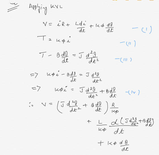
 Consider the system given below. The output is y(displacement from equilibrium position) and the input is V. (source voltage). The motor has an electrical constant Ke, a torque constant K, an armature inductance Lg and a resistance R. The rotor, shaft and disk together have inertia J and a viscous friction coefficient B. The disk has a radius ofr. (For the motor, assume that the torque is T = Ki,, and the back EMF is emf = KO). a. Derive...
A permanent magnet DC motor is supplied from a 12 V source and turns at 500...
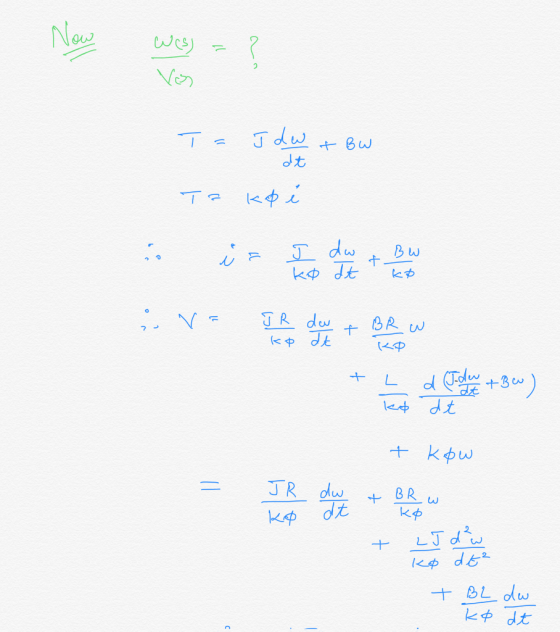
 A permanent magnet DC motor is supplied from a 12 V source and turns at 500 RPM (steady-state) experimentally determined as 0.1 Nms2 and the frictions are negligible. The electrical parameters of the rotor winding are measured 0.82, and 5mH. Obtain the transfer function of the motor by considering the armature voltage as input and shaft speed in rad/s as output. with an armature current of 1A. The moment of inertia is
 D.C. motor is shown below, where the inductance
L and the resistance R model the
armature circuit. The voltage
Vbrepresents the back-emf
which is proportional to dθ/dt via
Kf. The torque T
generated by the motor is proportional to the
i via a constant
Kt. In this application, let the
constants Kt =
Kf. The inertia J
represents the combined inertia of the motor and load. The viscous
friction acting on the output shaft is b. Attached
to the shaft...
D.C. motor is shown below, where the inductance
L and the resistance R model the
armature circuit. The voltage
Vbrepresents the back-emf
which is proportional to dθ/dt via
Kf. The torque T
generated by the motor is proportional to the
i via a constant
Kt. In this application, let the
constants Kt =
Kf. The inertia J
represents the combined inertia of the motor and load. The viscous
friction acting on the output shaft is b. Attached
to the shaft...
 D.C. motor is shown below, where the inductance
L and the resistance R model the
armature circuit. The voltage
Vbrepresents the back-emf
which is proportional to dθ/dt via
Kf. The torque T
generated by the motor is proportional to the
i via a constant
Kt. In this application, let the
constants Kt =
Kf. The inertia
Jrepresents the combined inertia of the motor and
load. The viscous friction acting on the output shaft is
b. Attached to the shaft is...
D.C. motor is shown below, where the inductance
L and the resistance R model the
armature circuit. The voltage
Vbrepresents the back-emf
which is proportional to dθ/dt via
Kf. The torque T
generated by the motor is proportional to the
i via a constant
Kt. In this application, let the
constants Kt =
Kf. The inertia
Jrepresents the combined inertia of the motor and
load. The viscous friction acting on the output shaft is
b. Attached to the shaft is...
 Q 1- 08 Pts) Figure below is a diagram of a DC motor connected in parnllel to a current source i,. The torque and back-EMF constants of the motor are Ko K respectively, the motor resistance is R, also modeled as connected in parallel, the motor inertia is 1- (not shown), and the motor inductance is negligible. The motor load is an inertia J with compliance (stiffness) K and viscous friction coefficient b, and it is attached a gear pair...
 01- (08 Pts) Figure below is a diagram of a DC motor connected in parallel to a current source is the torque and back-EMF constants of the motor are K. K respectively, the motor resistance is R, also modeled as connected in parallel, the motor inertia is I. (not shown), and the motor inductance is negligible. The motor load is an inertia compliance (stiffness) K and viscous friction coefficient b, and it is attached to the motor via a gear...
 Problem-5 (20 pts): Consider the DC servo motor shown in Figure-5. Assume that the input of the system is the applied armature voltage ea and the output is the load shaft position θ2. Assume also the following numerical values for the components: Ra-) Armature winding resistance = 0.2Ω La → Armature winding inductance = 0.1 mH Kb-) Back emf constant 0.05 Vs/rad K > Motor torque constant 0.06 Nm/A Jr Moment of inertia of the rotor of the motor =...
 Figure Q1(b) shows the simplified diagram of the armature controlled D.C. b) servomotors used in instruments and employed a fixed permane nt magnet field. The control signal is app lied to the amature terminals. The inductance of armature winding is negligible. Obtain the transfer function of the servo mot or (assume K, K, and K, are constant) i) (10marks) Derive a state spa ce model for the servomotor (armature resistance is 0.2) (5marks) i) La Fixed field (if) Ra ww00...
 2. (20 points) A field controlled DC motor model is given below where eaſt) is an applied input voltage, ia(t) is the armature current, Ra and La are the armature resistance and inductance, respectively, e(t) is a back (or counter) emf (electro-motive force) le (t) = K w here K is a motor (torque) constant, t(t) is the torque generated by the motor, w(t) is the angular velocity, 0(t) is the angular position, J represents the rotor inertia and load...
 please solve this problem with detail description.
A simple but practical feedback control system is shown below. It is a positioning system or position servo for a large video satellite antenna modeled as a mass having a large moment of inertia, J. An output potentiometer measures the output shaft position, converting the position to a proportional voltage according to vo-Kye. where, e is the output shaft angle in radians and vo is the output potentiometer voltage; Kp is the constant...
please solve this problem with detail description.
A simple but practical feedback control system is shown below. It is a positioning system or position servo for a large video satellite antenna modeled as a mass having a large moment of inertia, J. An output potentiometer measures the output shaft position, converting the position to a proportional voltage according to vo-Kye. where, e is the output shaft angle in radians and vo is the output potentiometer voltage; Kp is the constant...
 Consider the system given below. The output is y(displacement from equilibrium position) and the input is V. (source voltage). The motor has an electrical constant Ke, a torque constant K, an armature inductance Lg and a resistance R. The rotor, shaft and disk together have inertia J and a viscous friction coefficient B. The disk has a radius ofr. (For the motor, assume that the torque is T = Ki,, and the back EMF is emf = KO). a. Derive...
 A permanent magnet DC motor is supplied from a 12 V source and turns at 500 RPM (steady-state) experimentally determined as 0.1 Nms2 and the frictions are negligible. The electrical parameters of the rotor winding are measured 0.82, and 5mH. Obtain the transfer function of the motor by considering the armature voltage as input and shaft speed in rad/s as output. with an armature current of 1A. The moment of inertia is
Most questions answered within 3 hours.
-
A χ2-curve, looking at the relationship between age and hours
spent working at an office per...
asked 21 seconds ago -
The pH of a sample of water from a river is 5.0. A
sample of effluent from...
asked 45 minutes ago -
At the beginning of the period, the Fabricating Department
budgeted direct labor of $136,500 and equipment...
asked 1 hour ago -
Please answer all
____ 28. Rent control is usually
justified on the grounds that it protects...
asked 1 hour ago -
PARTS A-D HAVE BEEN ANSWERED. WAS TOLD TO REPOST. ONLY ANSWER
PARTS E and F.
A...
asked 1 hour ago -
2) You are given the task of finding a representation for a
circle in a drawing...
asked 2 hours ago -
STUDY QUESTION: Does use of diet drug fen-phen
(fenfluramine-phentermine) cause valvular heart disease?
HINT: Valvular heart...
asked 2 hours ago -
1. An object weighing 40 N rests on a surface. The coefficient
of friction is 0.35....
asked 3 hours ago -
Investor company owns 35% of investee company voting stock and
accounts for the investment under the...
asked 4 hours ago -
The number of major faults on a randomly chosen 1 km stretch of
highway has a...
asked 5 hours ago -
Consider the competitive environment of Starbuck's, Progressive
Insurance, a manufacturing firm with low turnover, or a...
asked 6 hours ago -
3. Gains from trade
Consider two neighbouring island countries called Euphoria and
Contente. They each have...
asked 7 hours ago