truss analysis using the stiffness method
Homework Answers
Request Answer!
We need at least 10 more requests to produce the answer.
0 / 10 have requested this problem solution
The more requests, the faster the answer.
13. Based on the stiffness method, determine the stiffness matrix K for the truss shown in...
 13. Based on the stiffness method, determine the stiffness matrix K for the truss shown in figure. Use the stiffness matrix to calculate the unknown displacement (D1 and D2) at the node where the load 5 kN and 10 kN are applied, and then determine the reactions at the pinned supports (Q3, Q4, Q5 and 26). Note that the degrees of freedom (DOFs) of the truss are indicated in the figure. Take EA as constant. The supports are pinned. 4....
Use the force method to determine the force in each member of the truss. Take a...
 Use the force method to determine the force in each member of the truss. Take a 2 kN, b 2 kN, c 20 kN and EA = 20000 kN (for all the members). a F В D 2 m A E 3 m 3 m Please fill in your solutions here: a) FAB kN b) FAC kN c) FBC kN d) FBD= kN e) FCD kN kN FCE kN g) FCF kN h) FDE kN i) FDF kN j) FEF...
Q2. Statically determinate or indeterminate truss analysis by the stiffness method. (50 marks) a) Determine the stiffness matrix of the whole truss given in problems 14.9 and 14.10 (p. 583). Indicate...
 Q2. Statically determinate or indeterminate truss analysis by
the stiffness method. (50 marks)
a) Determine the stiffness matrix of the whole truss given in
problems 14.9 and 14.10 (p. 583). Indicate the degrees-of freedom
in all the stiffness matrices. (18 marks)
b) Calculate all the nodal displacements and all the member forces
for the truss.
(16 marks)
14-9. Determine the stiffness matrix K for the trus Take A 0.0015 m2 and E 200 GPa for each member. 2 12 4...
Q2. Statically determinate or indeterminate truss analysis by
the stiffness method. (50 marks)
a) Determine the stiffness matrix of the whole truss given in
problems 14.9 and 14.10 (p. 583). Indicate the degrees-of freedom
in all the stiffness matrices. (18 marks)
b) Calculate all the nodal displacements and all the member forces
for the truss.
(16 marks)
14-9. Determine the stiffness matrix K for the trus Take A 0.0015 m2 and E 200 GPa for each member. 2 12 4...
Problem 2 [Required]: For the truss below (and using the Stiffness Method): (a) Determine the global...
 Problem 2 [Required]: For the truss below (and using the Stiffness Method): (a) Determine the global stiffness matrix; (b) Calculate the vertical and horizontal displacement at joint B; (c) Calculate the force in members 1 and 5; (d) Calculate the reaction forces. NOTE: Joint A is pinned and Joint D is a roller. AE is constant. Use the chart below for selecting near and far nodes and use the provided coordination numbers. u2 2m 5 2 kN 3 Element 2...
Using the Stiffness Method procedure identify nodes, elements and degrees of freedom (neglect axial stiffness) for the beam shown below. Form member and structure stiffness matrices and compute displ...
 Using the Stiffness Method procedure identify nodes, elements and degrees of freedom (neglect axial stiffness) for the beam shown below. Form member and structure stiffness matrices and compute displacements, reactions and internal forces developed in the beam Note that there is a hinge at B. Take E = 250 GPa, 1-2000 cm 10 kN 2 kN/m 5 kN-m 10 m
Using the Stiffness Method procedure identify nodes, elements and degrees of freedom (neglect axial stiffness) for the beam shown below....
Using the Stiffness Method procedure identify nodes, elements and degrees of freedom (neglect axial stiffness) for the beam shown below. Form member and structure stiffness matrices and compute displacements, reactions and internal forces developed in the beam Note that there is a hinge at B. Take E = 250 GPa, 1-2000 cm 10 kN 2 kN/m 5 kN-m 10 m
Using the Stiffness Method procedure identify nodes, elements and degrees of freedom (neglect axial stiffness) for the beam shown below....
Using the Stiffness Method procedure identify nodes, elements and degrees of freedom (neglect axial stiffness) for the beam shown below. Form member and structure stiffness matrices and compute di...
 Using the Stiffness Method procedure identify nodes, elements and degrees of freedom (neglect axial stiffness) for the beam shown below. Form member and structure stiffness matrices and compute displacements, reactions and internal forces developed in the beam. Note that there is a hinge at B. Take E= 250 G Pa, 1 = 2000 cm- 10 kN 5 kN-m 2 kN/m 10 m
Using the Stiffness Method procedure identify nodes, elements and degrees of freedom (neglect axial stiffness) for the beam...
Using the Stiffness Method procedure identify nodes, elements and degrees of freedom (neglect axial stiffness) for the beam shown below. Form member and structure stiffness matrices and compute displacements, reactions and internal forces developed in the beam. Note that there is a hinge at B. Take E= 250 G Pa, 1 = 2000 cm- 10 kN 5 kN-m 2 kN/m 10 m
Using the Stiffness Method procedure identify nodes, elements and degrees of freedom (neglect axial stiffness) for the beam...
Using the method of joints, determine the force in each member of the truss shown. State...
 Using the method of joints, determine the force in each member
of the truss shown. State whether each member is in tension or
compression.
7 kN 24 kN 7 kN B с А 0.8 m DO E F 8 kN -1.5 m- -1.5 m
Using the method of joints, determine the force in each member
of the truss shown. State whether each member is in tension or
compression.
7 kN 24 kN 7 kN B с А 0.8 m DO E F 8 kN -1.5 m- -1.5 m
Direct Stiffness Matrix method
 Using the direct stiffness matrix method analyse the truss as shown in the figure.use E= 2 x 10⁵ kN/m2L = 10 mA = 0.01 m2P = 10 kNat joint B is the hinge and at joint C is the roller.
P3 F E 3) Determine the force in members BC, BE, and EF of the truss...
 P3 F E 3) Determine the force in members BC, BE, and EF of the truss and state if these members are in tension or compression. Set Pi = 6 kN, P2= 9 kN, and Ps= 12 kN. 3 m D B С Draw and label a complete FBD of the section you choose to analyze. 3 m 3 m 3 m P1 P
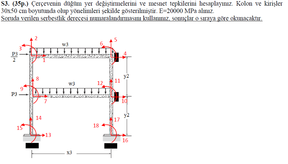
tatically determinate or indeterminate frame analysis by the stiffness method (45 marks) a) Determine the stiffine...
 tatically determinate or indeterminate frame analysis by the stiffness method (45 marks) a) Determine the stiffiness matrix of the frame of problems 16.5 and 16.6 (p. 619). Indicate the degrees-of freedom in all the stiffness matrices. b) D Q4. S (10 marks) etermine all the displacement components at node 2 and all the reactions including the reactions at node 2. Show all calculations. c) (18 marks) of the frame on the compression side showing all the salient values (5 marks)...
 13. Based on the stiffness method, determine the stiffness matrix K for the truss shown in figure. Use the stiffness matrix to calculate the unknown displacement (D1 and D2) at the node where the load 5 kN and 10 kN are applied, and then determine the reactions at the pinned supports (Q3, Q4, Q5 and 26). Note that the degrees of freedom (DOFs) of the truss are indicated in the figure. Take EA as constant. The supports are pinned. 4....
 Use the force method to determine the force in each member of the truss. Take a 2 kN, b 2 kN, c 20 kN and EA = 20000 kN (for all the members). a F В D 2 m A E 3 m 3 m Please fill in your solutions here: a) FAB kN b) FAC kN c) FBC kN d) FBD= kN e) FCD kN kN FCE kN g) FCF kN h) FDE kN i) FDF kN j) FEF...
 Q2. Statically determinate or indeterminate truss analysis by
the stiffness method. (50 marks)
a) Determine the stiffness matrix of the whole truss given in
problems 14.9 and 14.10 (p. 583). Indicate the degrees-of freedom
in all the stiffness matrices. (18 marks)
b) Calculate all the nodal displacements and all the member forces
for the truss.
(16 marks)
14-9. Determine the stiffness matrix K for the trus Take A 0.0015 m2 and E 200 GPa for each member. 2 12 4...
Q2. Statically determinate or indeterminate truss analysis by
the stiffness method. (50 marks)
a) Determine the stiffness matrix of the whole truss given in
problems 14.9 and 14.10 (p. 583). Indicate the degrees-of freedom
in all the stiffness matrices. (18 marks)
b) Calculate all the nodal displacements and all the member forces
for the truss.
(16 marks)
14-9. Determine the stiffness matrix K for the trus Take A 0.0015 m2 and E 200 GPa for each member. 2 12 4...
 Problem 2 [Required]: For the truss below (and using the Stiffness Method): (a) Determine the global stiffness matrix; (b) Calculate the vertical and horizontal displacement at joint B; (c) Calculate the force in members 1 and 5; (d) Calculate the reaction forces. NOTE: Joint A is pinned and Joint D is a roller. AE is constant. Use the chart below for selecting near and far nodes and use the provided coordination numbers. u2 2m 5 2 kN 3 Element 2...
 Using the Stiffness Method procedure identify nodes, elements and degrees of freedom (neglect axial stiffness) for the beam shown below. Form member and structure stiffness matrices and compute displacements, reactions and internal forces developed in the beam Note that there is a hinge at B. Take E = 250 GPa, 1-2000 cm 10 kN 2 kN/m 5 kN-m 10 m
Using the Stiffness Method procedure identify nodes, elements and degrees of freedom (neglect axial stiffness) for the beam shown below....
Using the Stiffness Method procedure identify nodes, elements and degrees of freedom (neglect axial stiffness) for the beam shown below. Form member and structure stiffness matrices and compute displacements, reactions and internal forces developed in the beam Note that there is a hinge at B. Take E = 250 GPa, 1-2000 cm 10 kN 2 kN/m 5 kN-m 10 m
Using the Stiffness Method procedure identify nodes, elements and degrees of freedom (neglect axial stiffness) for the beam shown below....
 Using the Stiffness Method procedure identify nodes, elements and degrees of freedom (neglect axial stiffness) for the beam shown below. Form member and structure stiffness matrices and compute displacements, reactions and internal forces developed in the beam. Note that there is a hinge at B. Take E= 250 G Pa, 1 = 2000 cm- 10 kN 5 kN-m 2 kN/m 10 m
Using the Stiffness Method procedure identify nodes, elements and degrees of freedom (neglect axial stiffness) for the beam...
Using the Stiffness Method procedure identify nodes, elements and degrees of freedom (neglect axial stiffness) for the beam shown below. Form member and structure stiffness matrices and compute displacements, reactions and internal forces developed in the beam. Note that there is a hinge at B. Take E= 250 G Pa, 1 = 2000 cm- 10 kN 5 kN-m 2 kN/m 10 m
Using the Stiffness Method procedure identify nodes, elements and degrees of freedom (neglect axial stiffness) for the beam...
 Using the method of joints, determine the force in each member
of the truss shown. State whether each member is in tension or
compression.
7 kN 24 kN 7 kN B с А 0.8 m DO E F 8 kN -1.5 m- -1.5 m
Using the method of joints, determine the force in each member
of the truss shown. State whether each member is in tension or
compression.
7 kN 24 kN 7 kN B с А 0.8 m DO E F 8 kN -1.5 m- -1.5 m
 P3 F E 3) Determine the force in members BC, BE, and EF of the truss and state if these members are in tension or compression. Set Pi = 6 kN, P2= 9 kN, and Ps= 12 kN. 3 m D B С Draw and label a complete FBD of the section you choose to analyze. 3 m 3 m 3 m P1 P
 tatically determinate or indeterminate frame analysis by the stiffness method (45 marks) a) Determine the stiffiness matrix of the frame of problems 16.5 and 16.6 (p. 619). Indicate the degrees-of freedom in all the stiffness matrices. b) D Q4. S (10 marks) etermine all the displacement components at node 2 and all the reactions including the reactions at node 2. Show all calculations. c) (18 marks) of the frame on the compression side showing all the salient values (5 marks)...
Most questions answered within 3 hours.
-
(63
#14)
which of the following statments best describes how chamging
the concentration of the substances...
asked 1 hour ago -
In the following reaction, which element is undergoing
oxidation: Na2SO3 + N2O --> N2 + Na2SO4...
asked 2 hours ago -
Which of the following pairs of ions have the same electron
configuration?
I: Br− and Se2−...
asked 4 hours ago -
The Foremost Composite Materials Company is planning a two-day
sales conference for October 19-20. The conference...
asked 5 hours ago -
3) Illustrate the observed pattern of relatedness of organisms
versus adaptations to specific conditions. This means...
asked 5 hours ago -
In winter a lake has a 0.35 m thick ice layer over 1.10 m of
water....
asked 6 hours ago -
Assuming the following has been encrypted with a Vigenere cipher
below, use the method(s) and assumptions...
asked 6 hours ago -
How would I use switch statements to write a program that will
take an input of...
asked 6 hours ago -
Imagine a reaction in which methane gas combusts at a constant
pressure of 1 atm and...
asked 6 hours ago -
Two parallel wires (each 12 m in length) are separated by a
distance of 0.065 m...
asked 6 hours ago -
Suppose there were three masses at the corner of uniform
equilateral triangle. The masses are m1...
asked 6 hours ago -
Situation: A building that is 618 m above the ground floor. How
many times would a...
asked 6 hours ago