
Homework Answers


![12 60-1之60 o 002 12-601o Go 4D0 ,-60200 200 Go 200 u oo So to E 200 -Go 4 0-12 60 O800 o Go 60 20o -6o Loo Lk] GD 30o03oo o -](http://img.homeworklib.com/images/e4d25d55-bffb-435c-9bd6-5592cb84b3a7.png?x-oss-process=image/resize,w_560)

![ve 16-ちㅋ 18 5 Nodal forces cn st ncde: [ there are ncfovcesto 5 [r] . [51, [토] 0 -16-67 16.67 0 .5 -19.5](http://img.homeworklib.com/images/f7bcf90c-35c2-4ec5-a76a-386ff88eb7f6.png?x-oss-process=image/resize,w_560)

Add Answer to:
Using the Stiffness Method procedure identify nodes, elements and degrees of freedom (neglect axial stiffness) for the beam shown below. Form member and structure stiffness matrices and compute displ...
Using the Stiffness Method procedure identify nodes, elements and degrees of freedom (neglect axial stiffness) for the beam shown below. Form member and structure stiffness matrices and compute di...
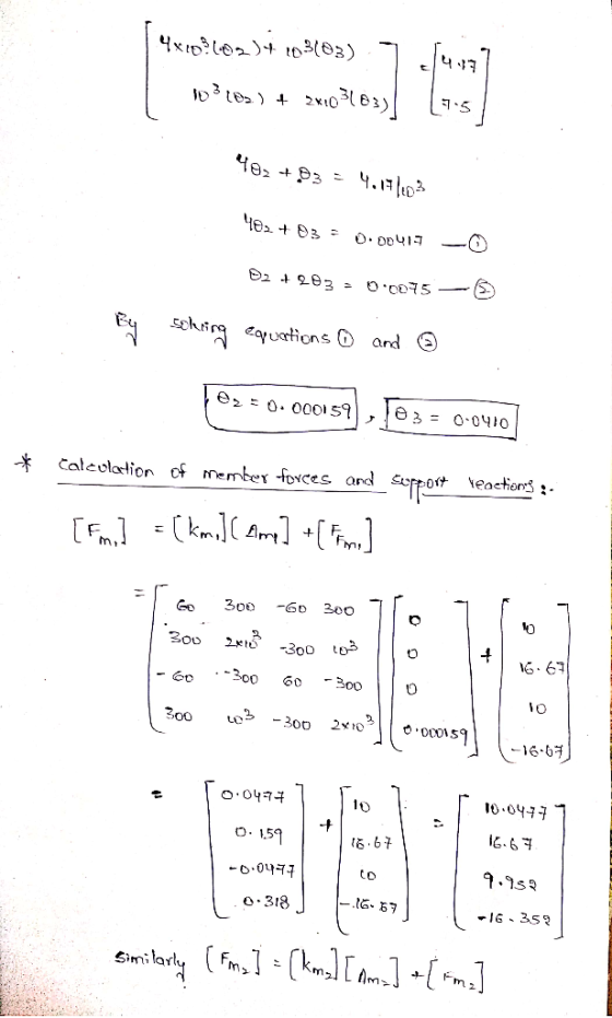
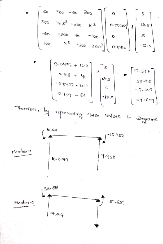
 Using the Stiffness Method procedure identify nodes, elements and degrees of freedom (neglect axial stiffness) for the beam shown below. Form member and structure stiffness matrices and compute displacements, reactions and internal forces developed in the beam. Note that there is a hinge at B. Take E= 250 G Pa, 1 = 2000 cm- 10 kN 5 kN-m 2 kN/m 10 m
Using the Stiffness Method procedure identify nodes, elements and degrees of freedom (neglect axial stiffness) for the beam...
Using the Stiffness Method procedure identify nodes, elements and degrees of freedom (neglect axial stiffness) for the beam shown below. Form member and structure stiffness matrices and compute displacements, reactions and internal forces developed in the beam. Note that there is a hinge at B. Take E= 250 G Pa, 1 = 2000 cm- 10 kN 5 kN-m 2 kN/m 10 m
Using the Stiffness Method procedure identify nodes, elements and degrees of freedom (neglect axial stiffness) for the beam...
Using the stiffness method, determine the axial forces within members and the displacements of jo...
 Using the stiffness method, determine the axial forces within
members and the displacements of joints of the truss shown in the
Figure 1. The truss was built using 50 mm x 50 mm x 3 mm SHS with
E= 200 GPa (approx). (Cross members BD and CE are not connected at
the middle)
(a) Show local stiffness matrices for each member and the
assembled global stiffness matrix. Show your step by step solution.
(30 Marks)
(b) Use an appropriate method...
Using the stiffness method, determine the axial forces within
members and the displacements of joints of the truss shown in the
Figure 1. The truss was built using 50 mm x 50 mm x 3 mm SHS with
E= 200 GPa (approx). (Cross members BD and CE are not connected at
the middle)
(a) Show local stiffness matrices for each member and the
assembled global stiffness matrix. Show your step by step solution.
(30 Marks)
(b) Use an appropriate method...
Use the stiffness method to analyse the structure shown below. For the beam ABC, E =...
 Use the stiffness method to analyse the structure shown below. For the beam ABC, E = 2 -108 kPa, A = 0,1 = 1.2e - 4 mº.. For the truss member DB, E = 200000000 kPa, A = 0.002 m². Also, take L = 6.5 m and o = 41 kN/m. 00 2 B с TIIL TE 3 Degrees of freedom D 2L Calculate the the bending moment at Joint B following the steps below: Part 1: Assemble the global...
Week 9. Question 1: Use the stiffness method to analyse the structure shown below. For the...
 Week 9. Question 1: Use the stiffness method to analyse the structure shown below. For the beam ABC, E = 2 -10% kPa, A -00, = 1.2e - 4 m. For the truss member DB, E = 200000000 kPa, A = 0.002 m. Also, take L54 m and w37 kN/m с 7 Degrees of freedom 22 Calculate the the bending moment at Joint B following the steps below. Part 1: Assemble the global structure stiffness matrix. Note that ABC is...
For the beam shown in below, determine the displacements and rotations at the nodes, the forces in each element, and reactions. Also, draw the shear force and bending moment diagrams 10 kN 2 E210 GPa...
 For the beam shown in below, determine the displacements and rotations at the nodes, the forces in each element, and reactions. Also, draw the shear force and bending moment diagrams 10 kN 2 E210 GPa .20 kN m
For the beam shown in below, determine the displacements and rotations at the nodes, the forces in each element, and reactions. Also, draw the shear force and bending moment diagrams 10 kN 2 E210 GPa .20 kN m
For the beam shown in below, determine the displacements and rotations at the nodes, the forces in each element, and reactions. Also, draw the shear force and bending moment diagrams 10 kN 2 E210 GPa .20 kN m
Analyse the beam shown in Figure 4 using the stiffiness method. Node D is fixed and...
 Analyse the beam shown in Figure 4 using the stiffiness method. Node D is fixed and node 2 and 3 are rollers. A uniform distributed load of 1 kN/m is acting on member 1 . And a load of 10 kN is acting at the middle of member2. EI is constant for all members a) Identify the force vector of the structure; [4 marks] b) Identify the displacement vector of the structure; [2 marks] c) Determine the stiffness matrices of...
Q2b Using the direct stiffness method, determine for the beam shown: a) the displacements and rotations...
 Q2b Using the direct stiffness method, determine for the beam shown: a) the displacements and rotations of the nodes, the shear forces and moments at the nodes b) Subsequently, draw the deflected shape, shear force and bending moment diagrams. 4m rM Take: El 5 X 10⁶ Nm2, F 10 kN and w 4 kN/m.
Week 9, Question 1: Use the stiffness method to analyse the structure shown below. For the...
 Week 9, Question 1: Use the stiffness method to analyse the structure shown below. For the beam ABC, E = 2-108 kPa, A=00, I = 1.2e - 4 mº.. For the truss member DB, E = 200000000 kPa, A=0.002 m2. Also, take L=6.9 m and w=30 kN/m. Degrees of freedom l- _-2L Calculate the the bending moment at Joint B following the steps below: Part 1: Assemble the global structure stiffness matrix. Note that ABC is infinitely rigid in the...
Week 9, Question 1: Use the stiffness method to analyse the structure shown below. For the...
 Week 9, Question 1: Use the stiffness method to analyse the structure shown below. For the beam ABC, E = 2.108 kPa, A = 0,1 = 1.2e – 4 mº.. For the truss member DB, E = 200000000 kPa, A = 0.002 m². Also, take L = 4.8 m and a = 25 kN/m. 0 2 A B C III 7 L 3 4 Degrees of freedom D L -2L Calculate the the bending moment at Joint B following the...
A plane structure consists of three truss elements connected to four nodes, as shown below. All t...
 A plane structure consists of three truss elements connected to four nodes, as shown below. All trusses have cross sectional area A -7.104 m2 and elastic modulus E = 210 GPa. The length of each truss element is L = 1 m. A point force, P -5 kN, is acting on node 4 L/2 3.1 Calculate the displacements at the nodes 3.2 Calculate the reaction forces 3.3 Calculate the stress in each bar
A plane structure consists of three truss...
A plane structure consists of three truss elements connected to four nodes, as shown below. All trusses have cross sectional area A -7.104 m2 and elastic modulus E = 210 GPa. The length of each truss element is L = 1 m. A point force, P -5 kN, is acting on node 4 L/2 3.1 Calculate the displacements at the nodes 3.2 Calculate the reaction forces 3.3 Calculate the stress in each bar
A plane structure consists of three truss...
 Using the Stiffness Method procedure identify nodes, elements and degrees of freedom (neglect axial stiffness) for the beam shown below. Form member and structure stiffness matrices and compute displacements, reactions and internal forces developed in the beam. Note that there is a hinge at B. Take E= 250 G Pa, 1 = 2000 cm- 10 kN 5 kN-m 2 kN/m 10 m
Using the Stiffness Method procedure identify nodes, elements and degrees of freedom (neglect axial stiffness) for the beam...
Using the Stiffness Method procedure identify nodes, elements and degrees of freedom (neglect axial stiffness) for the beam shown below. Form member and structure stiffness matrices and compute displacements, reactions and internal forces developed in the beam. Note that there is a hinge at B. Take E= 250 G Pa, 1 = 2000 cm- 10 kN 5 kN-m 2 kN/m 10 m
Using the Stiffness Method procedure identify nodes, elements and degrees of freedom (neglect axial stiffness) for the beam...
 Using the stiffness method, determine the axial forces within
members and the displacements of joints of the truss shown in the
Figure 1. The truss was built using 50 mm x 50 mm x 3 mm SHS with
E= 200 GPa (approx). (Cross members BD and CE are not connected at
the middle)
(a) Show local stiffness matrices for each member and the
assembled global stiffness matrix. Show your step by step solution.
(30 Marks)
(b) Use an appropriate method...
Using the stiffness method, determine the axial forces within
members and the displacements of joints of the truss shown in the
Figure 1. The truss was built using 50 mm x 50 mm x 3 mm SHS with
E= 200 GPa (approx). (Cross members BD and CE are not connected at
the middle)
(a) Show local stiffness matrices for each member and the
assembled global stiffness matrix. Show your step by step solution.
(30 Marks)
(b) Use an appropriate method...
 Use the stiffness method to analyse the structure shown below. For the beam ABC, E = 2 -108 kPa, A = 0,1 = 1.2e - 4 mº.. For the truss member DB, E = 200000000 kPa, A = 0.002 m². Also, take L = 6.5 m and o = 41 kN/m. 00 2 B с TIIL TE 3 Degrees of freedom D 2L Calculate the the bending moment at Joint B following the steps below: Part 1: Assemble the global...
 Week 9. Question 1: Use the stiffness method to analyse the structure shown below. For the beam ABC, E = 2 -10% kPa, A -00, = 1.2e - 4 m. For the truss member DB, E = 200000000 kPa, A = 0.002 m. Also, take L54 m and w37 kN/m с 7 Degrees of freedom 22 Calculate the the bending moment at Joint B following the steps below. Part 1: Assemble the global structure stiffness matrix. Note that ABC is...
 For the beam shown in below, determine the displacements and rotations at the nodes, the forces in each element, and reactions. Also, draw the shear force and bending moment diagrams 10 kN 2 E210 GPa .20 kN m
For the beam shown in below, determine the displacements and rotations at the nodes, the forces in each element, and reactions. Also, draw the shear force and bending moment diagrams 10 kN 2 E210 GPa .20 kN m
For the beam shown in below, determine the displacements and rotations at the nodes, the forces in each element, and reactions. Also, draw the shear force and bending moment diagrams 10 kN 2 E210 GPa .20 kN m
 Analyse the beam shown in Figure 4 using the stiffiness method. Node D is fixed and node 2 and 3 are rollers. A uniform distributed load of 1 kN/m is acting on member 1 . And a load of 10 kN is acting at the middle of member2. EI is constant for all members a) Identify the force vector of the structure; [4 marks] b) Identify the displacement vector of the structure; [2 marks] c) Determine the stiffness matrices of...
 Q2b Using the direct stiffness method, determine for the beam shown: a) the displacements and rotations of the nodes, the shear forces and moments at the nodes b) Subsequently, draw the deflected shape, shear force and bending moment diagrams. 4m rM Take: El 5 X 10⁶ Nm2, F 10 kN and w 4 kN/m.
 Week 9, Question 1: Use the stiffness method to analyse the structure shown below. For the beam ABC, E = 2-108 kPa, A=00, I = 1.2e - 4 mº.. For the truss member DB, E = 200000000 kPa, A=0.002 m2. Also, take L=6.9 m and w=30 kN/m. Degrees of freedom l- _-2L Calculate the the bending moment at Joint B following the steps below: Part 1: Assemble the global structure stiffness matrix. Note that ABC is infinitely rigid in the...
 Week 9, Question 1: Use the stiffness method to analyse the structure shown below. For the beam ABC, E = 2.108 kPa, A = 0,1 = 1.2e – 4 mº.. For the truss member DB, E = 200000000 kPa, A = 0.002 m². Also, take L = 4.8 m and a = 25 kN/m. 0 2 A B C III 7 L 3 4 Degrees of freedom D L -2L Calculate the the bending moment at Joint B following the...
 A plane structure consists of three truss elements connected to four nodes, as shown below. All trusses have cross sectional area A -7.104 m2 and elastic modulus E = 210 GPa. The length of each truss element is L = 1 m. A point force, P -5 kN, is acting on node 4 L/2 3.1 Calculate the displacements at the nodes 3.2 Calculate the reaction forces 3.3 Calculate the stress in each bar
A plane structure consists of three truss...
A plane structure consists of three truss elements connected to four nodes, as shown below. All trusses have cross sectional area A -7.104 m2 and elastic modulus E = 210 GPa. The length of each truss element is L = 1 m. A point force, P -5 kN, is acting on node 4 L/2 3.1 Calculate the displacements at the nodes 3.2 Calculate the reaction forces 3.3 Calculate the stress in each bar
A plane structure consists of three truss...
Most questions answered within 3 hours.
-
The free energy change for the following reaction at 25 °C, when
[Sn2+] = 1.17 M...
asked 14 minutes ago -
An MNE is this kind of industry when competition in one country
is essentially independent of...
asked 1 hour ago -
. For this set of questions, determine what
proportion of a normal distribution is located betweeneach...
asked 2 hours ago -
A college student is employed as a door-to-door newspaper
salesman. Historical data suggests that the student...
asked 3 hours ago -
MATLAB HW 11 problem using Switch Case and Input commands
Write a script file that calculates...
asked 3 hours ago -
Considering gravitational time dilation, calculate the time that
passes in Earth’s surface while 1 hour passes...
asked 3 hours ago -
Minitab Problem: Take the Lake Hume June rainfall data and find
use the processes outlined in...
asked 4 hours ago -
X Company is trying to decide whether to continue using old
equipment to make Product A...
asked 4 hours ago -
IN PYTHON ONLY !! Program 2: Re-work
program #5 (WeeklyHours) from the previous assignment such that...
asked 5 hours ago -
The average length of time between arrivals at a turnpike
toll-booth is 26 seconds. What is...
asked 6 hours ago -
(a) A piston at 6.1 atm contains a gas that occupies a volume of
3.5 L....
asked 8 hours ago -
Please answer true or false. Words
cannot be changed or added in to make it true...
asked 8 hours ago