

Homework Answers


| 1 | 2 | 3 | 4 | |
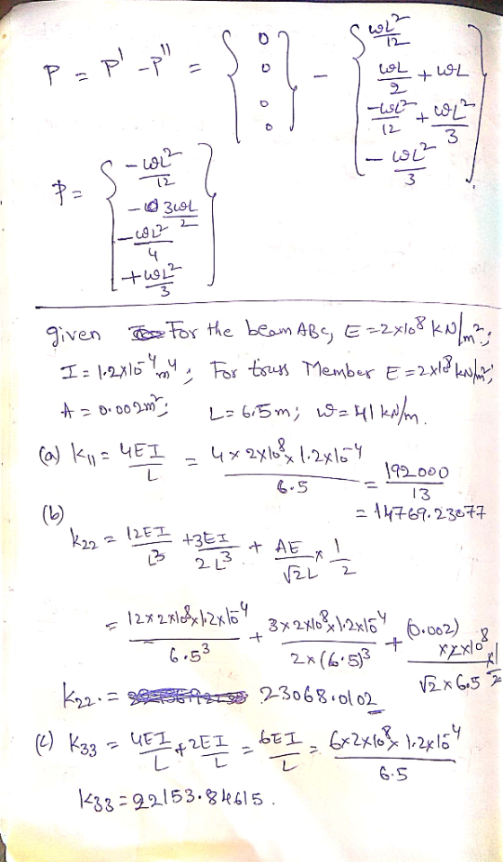
| 1 | 14769.231 | -3408.28 | 7384.615 | 0 |
| 2 | -3408.284 | 23068.01 | -2556.21 | 852.071 |
| 3 | 7384.6154 | -2556.21 | 22153.85 | 3692.308 |
| 4 | 0 | 852.071 | 3692.308 | 7384.615 |
| -144.354 |
| -399.75 |
| -433.063 |
| 577.4167 |
| 0.004988 |
| -0.02489 |
| -0.04101 |
| 0.101569 |
Add Answer to:
Use the stiffness method to analyse the structure shown below. For the beam ABC, E =...
Week 9, Question 1: Use the stiffness method to analyse the structure shown below. For the...
 Week 9, Question 1: Use the stiffness method to analyse the structure shown below. For the beam ABC, E = 2.108 kPa, A = 0,1 = 1.2e – 4 mº.. For the truss member DB, E = 200000000 kPa, A = 0.002 m². Also, take L = 4.8 m and a = 25 kN/m. 0 2 A B C III 7 L 3 4 Degrees of freedom D L -2L Calculate the the bending moment at Joint B following the...
Week 9, Question 1: Use the stiffness method to analyse the structure shown below. For the...
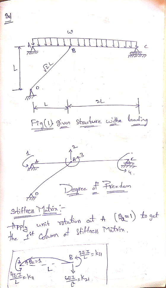
 Week 9, Question 1: Use the stiffness method to analyse the structure shown below. For the beam ABC, E = 2-108 kPa, A=00, I = 1.2e - 4 mº.. For the truss member DB, E = 200000000 kPa, A=0.002 m2. Also, take L=6.9 m and w=30 kN/m. Degrees of freedom l- _-2L Calculate the the bending moment at Joint B following the steps below: Part 1: Assemble the global structure stiffness matrix. Note that ABC is infinitely rigid in the...
Week 9. Question 1: Use the stiffness method to analyse the structure shown below. For the...
 Week 9. Question 1: Use the stiffness method to analyse the structure shown below. For the beam ABC, E = 2 -10% kPa, A -00, = 1.2e - 4 m. For the truss member DB, E = 200000000 kPa, A = 0.002 m. Also, take L54 m and w37 kN/m с 7 Degrees of freedom 22 Calculate the the bending moment at Joint B following the steps below. Part 1: Assemble the global structure stiffness matrix. Note that ABC is...
Use the stiffness method to analyse the elastic frame ABC shown below. Use a model made...
 Use the stiffness method to analyse the elastic frame ABC shown below. Use a model made up of 2 the elements (AB and CB) and the axis indicated in the figure. All members have the following properties: E = 2 -10% kPa, A = 0.005 m², 1 = 1.5e - 4 m. Also the lengths of the elements are the same: AB = BC = L = 3.1 m and 6 = 45 kN/m. ות 0 B 3 2 x...
Week 9, Question 2: Use the stiffness method to analyse the elastic frame ABC shown below....
 Week 9, Question 2: Use the stiffness method to analyse the elastic frame ABC shown below. Use a model made up of 2 the elements (AB and CB) and the axis indicated in the figure. All members have the following properties: E = 2 ·10kPa, A = 0.005 m², 1 = 1.5e – 4 m+.. Also the lengths of the elements are the same: AB = BC = L = 6.5 m and w = 12 kN/m. 0 А x...
Use the stiffness method to analyse the elastic frame ABC shown below. Use a model made...
 Use the stiffness method to analyse the elastic frame ABC shown below. Use a model made up of 2 the elements (AB and CB) and the axis indicated in the figure. All members have the following properties: E=2.108 kPa, A = 0.005 m², 1 = 1.5e - 4 m4. Also the lengths of the elements are the same: AB = BC = L = 4.7 m and w=17 kN/m. - B Structure, loading, member axes Degrees of freedom Calculate the...
Week 7. Question 1: Use the stiffness method to determine the horizontal and vertical displacements at...
 Week 7. Question 1: Use the stiffness method to determine the horizontal and vertical displacements at joint A. For all members, E-206.8 GPa and A - 1290 mm? Take a - 8 mandb-6.1 m B 2 انها 160 kN Solve the problem by following these steps Part 1) Calculate the stiffness matrix of each member in the global coordinate system. Check kna (the value at the second column and second row) in each member stiffness matrix a) Member 1: ky...
Analyse the beam shown in Figure 4 using the stiffiness method. Node D is fixed and...
 Analyse the beam shown in Figure 4 using the stiffiness method. Node D is fixed and node 2 and 3 are rollers. A uniform distributed load of 1 kN/m is acting on member 1 . And a load of 10 kN is acting at the middle of member2. EI is constant for all members a) Identify the force vector of the structure; [4 marks] b) Identify the displacement vector of the structure; [2 marks] c) Determine the stiffness matrices of...
 Week 9, Question 1: Use the stiffness method to analyse the structure shown below. For the beam ABC, E = 2.108 kPa, A = 0,1 = 1.2e – 4 mº.. For the truss member DB, E = 200000000 kPa, A = 0.002 m². Also, take L = 4.8 m and a = 25 kN/m. 0 2 A B C III 7 L 3 4 Degrees of freedom D L -2L Calculate the the bending moment at Joint B following the...
 Week 9, Question 1: Use the stiffness method to analyse the structure shown below. For the beam ABC, E = 2-108 kPa, A=00, I = 1.2e - 4 mº.. For the truss member DB, E = 200000000 kPa, A=0.002 m2. Also, take L=6.9 m and w=30 kN/m. Degrees of freedom l- _-2L Calculate the the bending moment at Joint B following the steps below: Part 1: Assemble the global structure stiffness matrix. Note that ABC is infinitely rigid in the...
 Week 9. Question 1: Use the stiffness method to analyse the structure shown below. For the beam ABC, E = 2 -10% kPa, A -00, = 1.2e - 4 m. For the truss member DB, E = 200000000 kPa, A = 0.002 m. Also, take L54 m and w37 kN/m с 7 Degrees of freedom 22 Calculate the the bending moment at Joint B following the steps below. Part 1: Assemble the global structure stiffness matrix. Note that ABC is...
 Use the stiffness method to analyse the elastic frame ABC shown below. Use a model made up of 2 the elements (AB and CB) and the axis indicated in the figure. All members have the following properties: E = 2 -10% kPa, A = 0.005 m², 1 = 1.5e - 4 m. Also the lengths of the elements are the same: AB = BC = L = 3.1 m and 6 = 45 kN/m. ות 0 B 3 2 x...
 Use the stiffness method to analyse the elastic frame ABC shown below. Use a model made up of 2 the elements (AB and CB) and the axis indicated in the figure. All members have the following properties: E = 2 -10% kPa, A = 0.005 m², 1 = 1.5e - 4 m. Also the lengths of the elements are the same: AB = BC = L = 3.1 m and 6 = 45 kN/m. ות 0 B 3 2 x...
 Use the stiffness method to analyse the elastic frame ABC shown below. Use a model made up of 2 the elements (AB and CB) and the axis indicated in the figure. All members have the following properties: E = 2 -10% kPa, A = 0.005 m², 1 = 1.5e - 4 m. Also the lengths of the elements are the same: AB = BC = L = 3.1 m and 6 = 45 kN/m. ות 0 B 3 2 x...
 Week 9, Question 2: Use the stiffness method to analyse the elastic frame ABC shown below. Use a model made up of 2 the elements (AB and CB) and the axis indicated in the figure. All members have the following properties: E = 2 ·10kPa, A = 0.005 m², 1 = 1.5e – 4 m+.. Also the lengths of the elements are the same: AB = BC = L = 6.5 m and w = 12 kN/m. 0 А x...
 Use the stiffness method to analyse the elastic frame ABC shown below. Use a model made up of 2 the elements (AB and CB) and the axis indicated in the figure. All members have the following properties: E=2.108 kPa, A = 0.005 m², 1 = 1.5e - 4 m4. Also the lengths of the elements are the same: AB = BC = L = 4.7 m and w=17 kN/m. - B Structure, loading, member axes Degrees of freedom Calculate the...
 Week 7. Question 1: Use the stiffness method to determine the horizontal and vertical displacements at joint A. For all members, E-206.8 GPa and A - 1290 mm? Take a - 8 mandb-6.1 m B 2 انها 160 kN Solve the problem by following these steps Part 1) Calculate the stiffness matrix of each member in the global coordinate system. Check kna (the value at the second column and second row) in each member stiffness matrix a) Member 1: ky...
 Analyse the beam shown in Figure 4 using the stiffiness method. Node D is fixed and node 2 and 3 are rollers. A uniform distributed load of 1 kN/m is acting on member 1 . And a load of 10 kN is acting at the middle of member2. EI is constant for all members a) Identify the force vector of the structure; [4 marks] b) Identify the displacement vector of the structure; [2 marks] c) Determine the stiffness matrices of...
Most questions answered within 3 hours.
-
Accent Software faces the following conditions. All of these
support Accent’s use of a market-penetration pricing...
asked 10 minutes ago -
A mathematically inclined friend emails you the following
instructions: "Meet me in the cafeteria the first...
asked 12 minutes ago -
A monopoly sells in two countries . The demand curves in the two
countries are p1...
asked 1 hour ago -
A .15kg rubber ball is bounced off a wall. Before hitting the
wall, the ball moves...
asked 1 hour ago -
A manufacturing company preparing to build a new plant is
considering three potential locations for it....
asked 1 hour ago -
B. If compound Y has approximately the same values of solubility
in toluene as compound X,...
asked 2 hours ago -
Oscar Inc. has inventory in Japan valued at 39,051,000 Yen one
year ago. One year ago...
asked 2 hours ago -
If Canada suffered from "fundamental disequilibrium," and its
government choose not to devalue its currency, a...
asked 2 hours ago -
4. How many input & output Key Value Pairs are passed into,
and emitted out of...
asked 2 hours ago -
Why would your heart not function well if constructed of
skeletal muscle? What is the particular...
asked 2 hours ago -
Please respond to this essay question in full essay form for
Chemistry 1102 Organic and Biochemistry:...
asked 2 hours ago -
Determine the head loss and velocity of flow in a water supply main
of 15.0 cm...
asked 2 hours ago