

Homework Answers


![. [K] [w] leh ✓ , 9-81 14.2.2 0 Fi-69-7 M. 16037 69.75 2 + 26.057 . 24 180 41 186 381 V2 O2 02 18:6 19.12 100 180 1810 109 18](http://img.homeworklib.com/questions/e4fd6580-e90b-11ea-b284-9160288feb30.png?x-oss-process=image/resize,w_560)

![- M3 w 103 10² [ 18.602 + 14.22 02] [18:6 x (-2.9 x10³) 112 + 19.22 xo.u687x16 o 3] - My yu.93 cum PAS PB Pc 113.26 IN IN MA](http://img.homeworklib.com/questions/e66d6890-e90b-11ea-8227-e16c5ff1e26c.png?x-oss-process=image/resize,w_560)
Add Answer to:
Use the stiffness method to analyse the elastic frame ABC shown below. Use a model made...
Use the stiffness method to analyse the elastic frame ABC shown below. Use a model made...
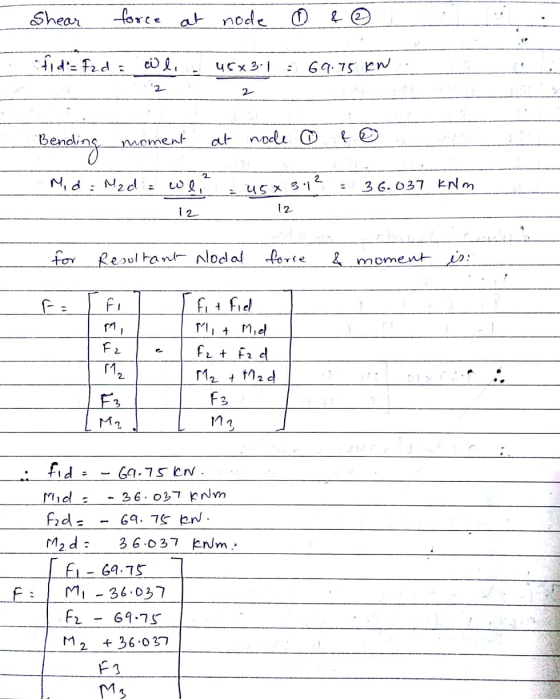
 Use the stiffness method to analyse the elastic frame ABC shown below. Use a model made up of 2 the elements (AB and CB) and the axis indicated in the figure. All members have the following properties: E = 2 -10% kPa, A = 0.005 m², 1 = 1.5e - 4 m. Also the lengths of the elements are the same: AB = BC = L = 3.1 m and 6 = 45 kN/m. ות 0 B 3 2 x...
Use the stiffness method to analyse the elastic frame ABC shown below. Use a model made...
 Use the stiffness method to analyse the elastic frame ABC shown below. Use a model made up of 2 the elements (AB and CB) and the axis indicated in the figure. All members have the following properties: E = 2 -10% kPa, A = 0.005 m², 1 = 1.5e - 4 m. Also the lengths of the elements are the same: AB = BC = L = 3.1 m and 6 = 45 kN/m. ות 0 B 3 2 x...
Week 9, Question 2: Use the stiffness method to analyse the elastic frame ABC shown below....
 Week 9, Question 2: Use the stiffness method to analyse the elastic frame ABC shown below. Use a model made up of 2 the elements (AB and CB) and the axis indicated in the figure. All members have the following properties: E = 2 ·10kPa, A = 0.005 m², 1 = 1.5e – 4 m+.. Also the lengths of the elements are the same: AB = BC = L = 6.5 m and w = 12 kN/m. 0 А x...
Use the stiffness method to analyse the elastic frame ABC shown below. Use a model made...
 Use the stiffness method to analyse the elastic frame ABC shown below. Use a model made up of 2 the elements (AB and CB) and the axis indicated in the figure. All members have the following properties: E=2.108 kPa, A = 0.005 m², 1 = 1.5e - 4 m4. Also the lengths of the elements are the same: AB = BC = L = 4.7 m and w=17 kN/m. - B Structure, loading, member axes Degrees of freedom Calculate the...
Week 9, Question 1: Use the stiffness method to analyse the structure shown below. For the...
 Week 9, Question 1: Use the stiffness method to analyse the structure shown below. For the beam ABC, E = 2-108 kPa, A=00, I = 1.2e - 4 mº.. For the truss member DB, E = 200000000 kPa, A=0.002 m2. Also, take L=6.9 m and w=30 kN/m. Degrees of freedom l- _-2L Calculate the the bending moment at Joint B following the steps below: Part 1: Assemble the global structure stiffness matrix. Note that ABC is infinitely rigid in the...
Use the stiffness method to analyse the structure shown below. For the beam ABC, E =...
 Use the stiffness method to analyse the structure shown below. For the beam ABC, E = 2 -108 kPa, A = 0,1 = 1.2e - 4 mº.. For the truss member DB, E = 200000000 kPa, A = 0.002 m². Also, take L = 6.5 m and o = 41 kN/m. 00 2 B с TIIL TE 3 Degrees of freedom D 2L Calculate the the bending moment at Joint B following the steps below: Part 1: Assemble the global...
Week 9, Question 1: Use the stiffness method to analyse the structure shown below. For the...
 Week 9, Question 1: Use the stiffness method to analyse the structure shown below. For the beam ABC, E = 2.108 kPa, A = 0,1 = 1.2e – 4 mº.. For the truss member DB, E = 200000000 kPa, A = 0.002 m². Also, take L = 4.8 m and a = 25 kN/m. 0 2 A B C III 7 L 3 4 Degrees of freedom D L -2L Calculate the the bending moment at Joint B following the...
Week 9. Question 1: Use the stiffness method to analyse the structure shown below. For the...
 Week 9. Question 1: Use the stiffness method to analyse the structure shown below. For the beam ABC, E = 2 -10% kPa, A -00, = 1.2e - 4 m. For the truss member DB, E = 200000000 kPa, A = 0.002 m. Also, take L54 m and w37 kN/m с 7 Degrees of freedom 22 Calculate the the bending moment at Joint B following the steps below. Part 1: Assemble the global structure stiffness matrix. Note that ABC is...
Week 7. Question 1: Use the stiffness method to determine the horizontal and vertical displacements at...
 Week 7. Question 1: Use the stiffness method to determine the horizontal and vertical displacements at joint A. For all members, E-206.8 GPa and A - 1290 mm? Take a - 8 mandb-6.1 m B 2 انها 160 kN Solve the problem by following these steps Part 1) Calculate the stiffness matrix of each member in the global coordinate system. Check kna (the value at the second column and second row) in each member stiffness matrix a) Member 1: ky...
Analyse the beam shown in Figure 4 using the stiffiness method. Node D is fixed and...
 Analyse the beam shown in Figure 4 using the stiffiness method. Node D is fixed and node 2 and 3 are rollers. A uniform distributed load of 1 kN/m is acting on member 1 . And a load of 10 kN is acting at the middle of member2. EI is constant for all members a) Identify the force vector of the structure; [4 marks] b) Identify the displacement vector of the structure; [2 marks] c) Determine the stiffness matrices of...
 Use the stiffness method to analyse the elastic frame ABC shown below. Use a model made up of 2 the elements (AB and CB) and the axis indicated in the figure. All members have the following properties: E = 2 -10% kPa, A = 0.005 m², 1 = 1.5e - 4 m. Also the lengths of the elements are the same: AB = BC = L = 3.1 m and 6 = 45 kN/m. ות 0 B 3 2 x...
 Use the stiffness method to analyse the elastic frame ABC shown below. Use a model made up of 2 the elements (AB and CB) and the axis indicated in the figure. All members have the following properties: E = 2 -10% kPa, A = 0.005 m², 1 = 1.5e - 4 m. Also the lengths of the elements are the same: AB = BC = L = 3.1 m and 6 = 45 kN/m. ות 0 B 3 2 x...
 Week 9, Question 2: Use the stiffness method to analyse the elastic frame ABC shown below. Use a model made up of 2 the elements (AB and CB) and the axis indicated in the figure. All members have the following properties: E = 2 ·10kPa, A = 0.005 m², 1 = 1.5e – 4 m+.. Also the lengths of the elements are the same: AB = BC = L = 6.5 m and w = 12 kN/m. 0 А x...
 Use the stiffness method to analyse the elastic frame ABC shown below. Use a model made up of 2 the elements (AB and CB) and the axis indicated in the figure. All members have the following properties: E=2.108 kPa, A = 0.005 m², 1 = 1.5e - 4 m4. Also the lengths of the elements are the same: AB = BC = L = 4.7 m and w=17 kN/m. - B Structure, loading, member axes Degrees of freedom Calculate the...
 Week 9, Question 1: Use the stiffness method to analyse the structure shown below. For the beam ABC, E = 2-108 kPa, A=00, I = 1.2e - 4 mº.. For the truss member DB, E = 200000000 kPa, A=0.002 m2. Also, take L=6.9 m and w=30 kN/m. Degrees of freedom l- _-2L Calculate the the bending moment at Joint B following the steps below: Part 1: Assemble the global structure stiffness matrix. Note that ABC is infinitely rigid in the...
 Use the stiffness method to analyse the structure shown below. For the beam ABC, E = 2 -108 kPa, A = 0,1 = 1.2e - 4 mº.. For the truss member DB, E = 200000000 kPa, A = 0.002 m². Also, take L = 6.5 m and o = 41 kN/m. 00 2 B с TIIL TE 3 Degrees of freedom D 2L Calculate the the bending moment at Joint B following the steps below: Part 1: Assemble the global...
 Week 9, Question 1: Use the stiffness method to analyse the structure shown below. For the beam ABC, E = 2.108 kPa, A = 0,1 = 1.2e – 4 mº.. For the truss member DB, E = 200000000 kPa, A = 0.002 m². Also, take L = 4.8 m and a = 25 kN/m. 0 2 A B C III 7 L 3 4 Degrees of freedom D L -2L Calculate the the bending moment at Joint B following the...
 Week 9. Question 1: Use the stiffness method to analyse the structure shown below. For the beam ABC, E = 2 -10% kPa, A -00, = 1.2e - 4 m. For the truss member DB, E = 200000000 kPa, A = 0.002 m. Also, take L54 m and w37 kN/m с 7 Degrees of freedom 22 Calculate the the bending moment at Joint B following the steps below. Part 1: Assemble the global structure stiffness matrix. Note that ABC is...
 Week 7. Question 1: Use the stiffness method to determine the horizontal and vertical displacements at joint A. For all members, E-206.8 GPa and A - 1290 mm? Take a - 8 mandb-6.1 m B 2 انها 160 kN Solve the problem by following these steps Part 1) Calculate the stiffness matrix of each member in the global coordinate system. Check kna (the value at the second column and second row) in each member stiffness matrix a) Member 1: ky...
 Analyse the beam shown in Figure 4 using the stiffiness method. Node D is fixed and node 2 and 3 are rollers. A uniform distributed load of 1 kN/m is acting on member 1 . And a load of 10 kN is acting at the middle of member2. EI is constant for all members a) Identify the force vector of the structure; [4 marks] b) Identify the displacement vector of the structure; [2 marks] c) Determine the stiffness matrices of...
Most questions answered within 3 hours.
-
Two ice skaters suddenly push off against one another starting
from a stationary position. The 45...
asked 46 seconds from now -
What is the Larmor frequency for a proton in a magnetic field of
B0 = 14.0...
asked 4 seconds ago -
Problem 03.019 Annual Worth Calculations
Find the value of x that makes the equivalent annual
worth...
asked 15 minutes ago -
Under common law, right of survivorship was automatically a
feature of which type of co-tenancy?
a....
asked 12 minutes ago -
Are there such things as microscopic multicellular animal
parasites? If so, please give examples.
asked 10 minutes ago -
At 1 bar, how much energy is required to heat 61.0 g of H2O(s)
at −12.0...
asked 32 minutes ago -
Find the mixed-strategy equilibrium to the Battle of the sexes
game in Figure 5.1 below
Hockey...
asked 34 minutes ago -
Use the following information to answer the next three
questions.
QUESTION 5
As of today, the...
asked 40 minutes ago -
Using the specific identification method: Date Units purchased
Cost per unit Ending inventory March 1 15...
asked 42 minutes ago -
PLEASE HELP, NO ONE IS ANSWERING MY QUESTION AND IT IS SUE TODAY
WORTH 20% OF...
asked 57 minutes ago -
α = 0.0007889 T, I = 2.9 A
Other Magnetic Fields: First, based on your
value...
asked 56 minutes ago -
This assignment is a continuation of the 2nd one. You as a HR
Manager, select an...
asked 59 minutes ago