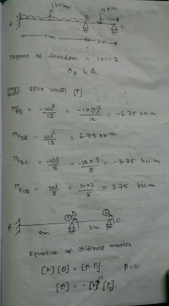
![Analyse the beam shown in Figure 4 using the stiffiness method. Node D is fixed and node 2 and 3 are rollers. A uniform distributed load of 1 kN/m is acting on member 1 . And a load of 10 kN is acting at the middle of member2. EI is constant for all members a) Identify the force vector of the structure; [4 marks] b) Identify the displacement vector of the structure; [2 marks] c) Determine the stiffness matrices of the members; [2 marks] d) Assemble the global stiffness matrix of the structure; [ 2 marks] e) Establish the force-displacement relationship and calculate the unknown displacements; [6 marks] Calculate the reaction forces at supports. [ 4 marks] 10 kN 6 m 1 kN/m 5 9 m Figure 4](http://img.homeworklib.com/questions/d4f18e30-1264-11ec-b989-4f9e980fef30.png?x-oss-process=image/resize,w_560)
Homework Answers

Add Answer to:
Analyse the beam shown in Figure 4 using the stiffiness method. Node D is fixed and...
Use the stiffness method to analyse the structure shown below. For the beam ABC, E =...
 Use the stiffness method to analyse the structure shown below. For the beam ABC, E = 2 -108 kPa, A = 0,1 = 1.2e - 4 mº.. For the truss member DB, E = 200000000 kPa, A = 0.002 m². Also, take L = 6.5 m and o = 41 kN/m. 00 2 B с TIIL TE 3 Degrees of freedom D 2L Calculate the the bending moment at Joint B following the steps below: Part 1: Assemble the global...
Question 4 The plane truss is subjected to a load as shown in Figure 4. Take E = 200 GPa and cross sectional areas of m...
 Question 4 The plane truss is subjected to a load as shown in Figure 4. Take E = 200 GPa and cross sectional areas of members 1, 2 and 3 as 150, 250 and 200 mm2 respectively a) Assemble the upper triangular part of the global stiffness matrix for the truss. b) Determine the horizontal and vertical displacements at node 4. c) Calculate the forces in each member of the truss. (25 marks) 20 kN 3 600 4 3 1.5m...
Analyse the ten members truss structure shown in Figure 02 using Compatibility Method and calculate the...
 Analyse the ten members truss structure shown in Figure 02 using Compatibility Method and calculate the axial force acting on member EC Take the Young's Modulus and the cross-sectional area of each member to be constant. 2(a) (15 marks 5 m 20 35 kN Figure Q2: Ten members truss b) Find the force in member BC 3 marks) Find the force in member BF 2 marks)
SAN4701 JAN/FEB 2015 QUESTION 1 The truss shown in Figure 1 is hinged at C, B and D It is acted upon at node A by a ver...
 SAN4701 JAN/FEB 2015 QUESTION 1 The truss shown in Figure 1 is hinged at C, B and D It is acted upon at node A by a vertically downward force of 3 kN and a honzontal force of 5 kN as shown in Figure 1 Use the method of strffness matrix and analyse for the following (a) Displacement at node A (16) (b) Reaction at the supports (c) Member forces (15) EA 300 x 103 kN and is constant for...
The plane truss is subjected to a load as shown in Figure 4. Take E = 200 GPa and cross sectional areas of members 1, 2...
 The plane truss is subjected to a load as shown in Figure 4. Take E = 200 GPa and cross sectional areas of members 1, 2 and 3 as 150, 250 and 200 mm2 respectively a) Assemble the upper triangular part of the global stiffness matrix for the truss b) Determine the horizontal and vertical displacements at node 4 c) Calculate the forces in each member of the truss. (25 marks) 20 kN 3 60° 4 1.5m 2 2 20m...
Use the stiffness method to analyse the elastic frame ABC shown below. Use a model made...
 Use the stiffness method to analyse the elastic frame ABC shown below. Use a model made up of 2 the elements (AB and CB) and the axis indicated in the figure. All members have the following properties: E = 2 -10% kPa, A = 0.005 m², 1 = 1.5e - 4 m. Also the lengths of the elements are the same: AB = BC = L = 3.1 m and 6 = 45 kN/m. ות 0 B 3 2 x...
Week 9, Question 2: Use the stiffness method to analyse the elastic frame ABC shown below....
 Week 9, Question 2: Use the stiffness method to analyse the elastic frame ABC shown below. Use a model made up of 2 the elements (AB and CB) and the axis indicated in the figure. All members have the following properties: E = 2 ·10kPa, A = 0.005 m², 1 = 1.5e – 4 m+.. Also the lengths of the elements are the same: AB = BC = L = 6.5 m and w = 12 kN/m. 0 А x...
2. For the pin-jointed truss shown in Figure Q2.1 applied at node 4. The Young's modulus E(GPa) is the same for...
 2. For the pin-jointed truss shown in Figure Q2.1 applied at node 4. The Young's modulus E(GPa) is the same for the three truss vertical downward force P(kN) is a members. The cross sectional area of each of the truss members is indicated below and expressed in terms of a constant A. By using the stiffness method: (a) Compute the reduced stiffness matrix Kg [5 marks [10 marks (b) Calculate the global displacements of node 4 in terms of P,...
 Use the stiffness method to analyse the structure shown below. For the beam ABC, E = 2 -108 kPa, A = 0,1 = 1.2e - 4 mº.. For the truss member DB, E = 200000000 kPa, A = 0.002 m². Also, take L = 6.5 m and o = 41 kN/m. 00 2 B с TIIL TE 3 Degrees of freedom D 2L Calculate the the bending moment at Joint B following the steps below: Part 1: Assemble the global...
 Question 4 The plane truss is subjected to a load as shown in Figure 4. Take E = 200 GPa and cross sectional areas of members 1, 2 and 3 as 150, 250 and 200 mm2 respectively a) Assemble the upper triangular part of the global stiffness matrix for the truss. b) Determine the horizontal and vertical displacements at node 4. c) Calculate the forces in each member of the truss. (25 marks) 20 kN 3 600 4 3 1.5m...
 Analyse the ten members truss structure shown in Figure 02 using Compatibility Method and calculate the axial force acting on member EC Take the Young's Modulus and the cross-sectional area of each member to be constant. 2(a) (15 marks 5 m 20 35 kN Figure Q2: Ten members truss b) Find the force in member BC 3 marks) Find the force in member BF 2 marks)
 SAN4701 JAN/FEB 2015 QUESTION 1 The truss shown in Figure 1 is hinged at C, B and D It is acted upon at node A by a vertically downward force of 3 kN and a honzontal force of 5 kN as shown in Figure 1 Use the method of strffness matrix and analyse for the following (a) Displacement at node A (16) (b) Reaction at the supports (c) Member forces (15) EA 300 x 103 kN and is constant for...
 The plane truss is subjected to a load as shown in Figure 4. Take E = 200 GPa and cross sectional areas of members 1, 2 and 3 as 150, 250 and 200 mm2 respectively a) Assemble the upper triangular part of the global stiffness matrix for the truss b) Determine the horizontal and vertical displacements at node 4 c) Calculate the forces in each member of the truss. (25 marks) 20 kN 3 60° 4 1.5m 2 2 20m...
 Use the stiffness method to analyse the elastic frame ABC shown below. Use a model made up of 2 the elements (AB and CB) and the axis indicated in the figure. All members have the following properties: E = 2 -10% kPa, A = 0.005 m², 1 = 1.5e - 4 m. Also the lengths of the elements are the same: AB = BC = L = 3.1 m and 6 = 45 kN/m. ות 0 B 3 2 x...
 Use the stiffness method to analyse the elastic frame ABC shown below. Use a model made up of 2 the elements (AB and CB) and the axis indicated in the figure. All members have the following properties: E = 2 -10% kPa, A = 0.005 m², 1 = 1.5e - 4 m. Also the lengths of the elements are the same: AB = BC = L = 3.1 m and 6 = 45 kN/m. ות 0 B 3 2 x...
 Use the stiffness method to analyse the elastic frame ABC shown below. Use a model made up of 2 the elements (AB and CB) and the axis indicated in the figure. All members have the following properties: E = 2 -10% kPa, A = 0.005 m², 1 = 1.5e - 4 m. Also the lengths of the elements are the same: AB = BC = L = 3.1 m and 6 = 45 kN/m. ות 0 B 3 2 x...
 Week 9, Question 2: Use the stiffness method to analyse the elastic frame ABC shown below. Use a model made up of 2 the elements (AB and CB) and the axis indicated in the figure. All members have the following properties: E = 2 ·10kPa, A = 0.005 m², 1 = 1.5e – 4 m+.. Also the lengths of the elements are the same: AB = BC = L = 6.5 m and w = 12 kN/m. 0 А x...
 2. For the pin-jointed truss shown in Figure Q2.1 applied at node 4. The Young's modulus E(GPa) is the same for the three truss vertical downward force P(kN) is a members. The cross sectional area of each of the truss members is indicated below and expressed in terms of a constant A. By using the stiffness method: (a) Compute the reduced stiffness matrix Kg [5 marks [10 marks (b) Calculate the global displacements of node 4 in terms of P,...
Most questions answered within 3 hours.
-
(63
#14)
which of the following statments best describes how chamging
the concentration of the substances...
asked 24 minutes ago -
In the following reaction, which element is undergoing
oxidation: Na2SO3 + N2O --> N2 + Na2SO4...
asked 1 hour ago -
Which of the following pairs of ions have the same electron
configuration?
I: Br− and Se2−...
asked 3 hours ago -
The Foremost Composite Materials Company is planning a two-day
sales conference for October 19-20. The conference...
asked 4 hours ago -
3) Illustrate the observed pattern of relatedness of organisms
versus adaptations to specific conditions. This means...
asked 4 hours ago -
In winter a lake has a 0.35 m thick ice layer over 1.10 m of
water....
asked 5 hours ago -
Assuming the following has been encrypted with a Vigenere cipher
below, use the method(s) and assumptions...
asked 5 hours ago -
How would I use switch statements to write a program that will
take an input of...
asked 5 hours ago -
Imagine a reaction in which methane gas combusts at a constant
pressure of 1 atm and...
asked 5 hours ago -
Two parallel wires (each 12 m in length) are separated by a
distance of 0.065 m...
asked 5 hours ago -
Suppose there were three masses at the corner of uniform
equilateral triangle. The masses are m1...
asked 5 hours ago -
Situation: A building that is 618 m above the ground floor. How
many times would a...
asked 5 hours ago