
Homework Answers


Add Answer to:
2. For the pin-jointed truss shown in Figure Q2.1 applied at node 4. The Young's modulus E(GPa) is the same for...
The plane truss is subjected to a load as shown in Figure 4. Take E = 200 GPa and cross sectional areas of members 1, 2...
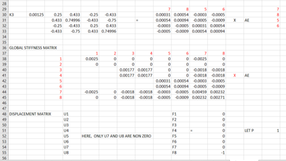
 The plane truss is subjected to a load as shown in Figure 4. Take E = 200 GPa and cross sectional areas of members 1, 2 and 3 as 150, 250 and 200 mm2 respectively a) Assemble the upper triangular part of the global stiffness matrix for the truss b) Determine the horizontal and vertical displacements at node 4 c) Calculate the forces in each member of the truss. (25 marks) 20 kN 3 60° 4 1.5m 2 2 20m...
Question 4 The plane truss is subjected to a load as shown in Figure 4. Take E = 200 GPa and cross sectional areas of m...
 Question 4 The plane truss is subjected to a load as shown in Figure 4. Take E = 200 GPa and cross sectional areas of members 1, 2 and 3 as 150, 250 and 200 mm2 respectively a) Assemble the upper triangular part of the global stiffness matrix for the truss. b) Determine the horizontal and vertical displacements at node 4. c) Calculate the forces in each member of the truss. (25 marks) 20 kN 3 600 4 3 1.5m...
Q1 The pin-jointed wood truss shown in Figure Q1a is subjected to a point load P...
 Q1 The pin-jointed wood truss shown in Figure Q1a is subjected to a point load P 24 kN at joint B a) Show that the truss is statically determinant. Indicate zero force members. Determine the force in members BC, CF, GF of the truss [10 marks] b) The truss is made of wooden joists (Young modulus E 10 GPa) with a rectangular cross-section having dimensions of 47mm × 150mm. The vertical displacement of joint B is measured to be 10...
Please solve this question clearly and step by step. Thank you 2. A truss assembly shown...
 Please solve this question clearly and step by step.
Thank you
2. A truss assembly shown in Figure Q2 below is made of aluminum alloy that has a modulus of elasticity, E = 69 GPa. member is 225 mm2 The cross sectional area of each 4300 N (0, 40) m (40, 40) m 2 500 N 3 (0, 0) FIGURE Q2 Determine the global stiffness matrix for the truss assembly. a. [10 marks] Determine the displacement at node 3. b....
Please solve this question clearly and step by step.
Thank you
2. A truss assembly shown in Figure Q2 below is made of aluminum alloy that has a modulus of elasticity, E = 69 GPa. member is 225 mm2 The cross sectional area of each 4300 N (0, 40) m (40, 40) m 2 500 N 3 (0, 0) FIGURE Q2 Determine the global stiffness matrix for the truss assembly. a. [10 marks] Determine the displacement at node 3. b....
Figure Q5(a) shows a plane truss supported by a horizontal spring at the top node. The...
 Figure Q5(a) shows a plane truss supported by a horizontal spring at the top node. The truss members are of a solid circular cross section having a diameter of 20 mm and an elastic modulus (E) of 80 GPa (10° N/m2). The spring has a stiffness constant of k-2000 kN/m. A point load of 15 kN is applied at the top node. The direction of the load is indicated in the figure. The code numbers for elements, nodes, DOFS, and...
please answer question 2a and 2b with clear steps and remarks (a) For the pin-jointed truss...
 please answer question 2a and 2b with clear steps and
remarks
(a) For the pin-jointed truss under design loads shown in Figure 2(a), member BC, AC and AD using the Method of Sections. Indicate whether the members are in tension (T) or compression (C) calculate the forces in 20 kN 70 kN 45° 45° 45° 45 80 kN 45° 45 4m 4m 4m L 4m 4m Figure 2(a) (b) A sample of a steel member was taken for tensile testing...
please answer question 2a and 2b with clear steps and
remarks
(a) For the pin-jointed truss under design loads shown in Figure 2(a), member BC, AC and AD using the Method of Sections. Indicate whether the members are in tension (T) or compression (C) calculate the forces in 20 kN 70 kN 45° 45° 45° 45 80 kN 45° 45 4m 4m 4m L 4m 4m Figure 2(a) (b) A sample of a steel member was taken for tensile testing...
Question Four: For the pin-jointed truss shown in Figure 4, 3m 12 KN 3m 30 kN 3m 15 kN 4m 4m 3m 3m 6m Figure 4. Calcula...
 Question Four: For the pin-jointed truss shown in Figure 4, 3m 12 KN 3m 30 kN 3m 15 kN 4m 4m 3m 3m 6m Figure 4. Calculate the reactions at A and B. (a) By inspection (involving no calculations), list all the zero force members. (b) (c) By method of joints, analyse joints T, S and N to determine the force in members ST NT, RS, SN, MN and RN. In your answer, you must state whether the members are...
080 Solid Mechanics.pdf Download Print > Save to OneDrive Question 4 The pin-jointed truss shown in...
 080 Solid Mechanics.pdf Download Print > Save to OneDrive Question 4 The pin-jointed truss shown in Figure Q4 lies in a vertical plane and is pinned to a rigid support at A and a roller support at D. All merobers have the same cross-section, A, and Young's modulus, E. Using the Virtual Work Method, calculate the vertical deflection at C. (20 marks) B 2 C D А 6W 2L 21 Figure Q4
The truss shown in the figure is constructed from three aluminum alloy members, each having a...
 The truss shown in the figure is constructed from three aluminum alloy members, each having a cross-sectional area of A 800 mm2 and an elastic modulus of E 70 GPa. Assume that a 4.0 m, b 10.5 m, and c 5.0 m. Calculate the horizontal displacement of roller Bwhen the truss supports a load of P 14 kN B X a
The truss shown in the figure is constructed from three aluminum alloy members, each having a cross-sectional area of...
The truss shown in the figure is constructed from three aluminum alloy members, each having a cross-sectional area of A 800 mm2 and an elastic modulus of E 70 GPa. Assume that a 4.0 m, b 10.5 m, and c 5.0 m. Calculate the horizontal displacement of roller Bwhen the truss supports a load of P 14 kN B X a
The truss shown in the figure is constructed from three aluminum alloy members, each having a cross-sectional area of...
SAN4701 JAN/FE8 2017 QUESTION 1 1 is having a hinge support at 1 and a roller support at 2. (E - 200 GPa) for all the m...
 SAN4701 JAN/FE8 2017 QUESTION 1 1 is having a hinge support at 1 and a roller support at 2. (E - 200 GPa) for all the members and the members 1, d 3 have their cross sectional areas as 4000 mm2, 4000 mm2 and 6000 mm2 The truss shown in Figure Assuming that E is constant respectively, use the matrix stiffness method to determine the following Number of degrees of freedom. a. (15) b. Structure stiffness matrıx. (10) c Member...
 The plane truss is subjected to a load as shown in Figure 4. Take E = 200 GPa and cross sectional areas of members 1, 2 and 3 as 150, 250 and 200 mm2 respectively a) Assemble the upper triangular part of the global stiffness matrix for the truss b) Determine the horizontal and vertical displacements at node 4 c) Calculate the forces in each member of the truss. (25 marks) 20 kN 3 60° 4 1.5m 2 2 20m...
 Question 4 The plane truss is subjected to a load as shown in Figure 4. Take E = 200 GPa and cross sectional areas of members 1, 2 and 3 as 150, 250 and 200 mm2 respectively a) Assemble the upper triangular part of the global stiffness matrix for the truss. b) Determine the horizontal and vertical displacements at node 4. c) Calculate the forces in each member of the truss. (25 marks) 20 kN 3 600 4 3 1.5m...
 Q1 The pin-jointed wood truss shown in Figure Q1a is subjected to a point load P 24 kN at joint B a) Show that the truss is statically determinant. Indicate zero force members. Determine the force in members BC, CF, GF of the truss [10 marks] b) The truss is made of wooden joists (Young modulus E 10 GPa) with a rectangular cross-section having dimensions of 47mm × 150mm. The vertical displacement of joint B is measured to be 10...
 Please solve this question clearly and step by step.
Thank you
2. A truss assembly shown in Figure Q2 below is made of aluminum alloy that has a modulus of elasticity, E = 69 GPa. member is 225 mm2 The cross sectional area of each 4300 N (0, 40) m (40, 40) m 2 500 N 3 (0, 0) FIGURE Q2 Determine the global stiffness matrix for the truss assembly. a. [10 marks] Determine the displacement at node 3. b....
Please solve this question clearly and step by step.
Thank you
2. A truss assembly shown in Figure Q2 below is made of aluminum alloy that has a modulus of elasticity, E = 69 GPa. member is 225 mm2 The cross sectional area of each 4300 N (0, 40) m (40, 40) m 2 500 N 3 (0, 0) FIGURE Q2 Determine the global stiffness matrix for the truss assembly. a. [10 marks] Determine the displacement at node 3. b....
 Figure Q5(a) shows a plane truss supported by a horizontal spring at the top node. The truss members are of a solid circular cross section having a diameter of 20 mm and an elastic modulus (E) of 80 GPa (10° N/m2). The spring has a stiffness constant of k-2000 kN/m. A point load of 15 kN is applied at the top node. The direction of the load is indicated in the figure. The code numbers for elements, nodes, DOFS, and...
 please answer question 2a and 2b with clear steps and
remarks
(a) For the pin-jointed truss under design loads shown in Figure 2(a), member BC, AC and AD using the Method of Sections. Indicate whether the members are in tension (T) or compression (C) calculate the forces in 20 kN 70 kN 45° 45° 45° 45 80 kN 45° 45 4m 4m 4m L 4m 4m Figure 2(a) (b) A sample of a steel member was taken for tensile testing...
please answer question 2a and 2b with clear steps and
remarks
(a) For the pin-jointed truss under design loads shown in Figure 2(a), member BC, AC and AD using the Method of Sections. Indicate whether the members are in tension (T) or compression (C) calculate the forces in 20 kN 70 kN 45° 45° 45° 45 80 kN 45° 45 4m 4m 4m L 4m 4m Figure 2(a) (b) A sample of a steel member was taken for tensile testing...
 Question Four: For the pin-jointed truss shown in Figure 4, 3m 12 KN 3m 30 kN 3m 15 kN 4m 4m 3m 3m 6m Figure 4. Calculate the reactions at A and B. (a) By inspection (involving no calculations), list all the zero force members. (b) (c) By method of joints, analyse joints T, S and N to determine the force in members ST NT, RS, SN, MN and RN. In your answer, you must state whether the members are...
 080 Solid Mechanics.pdf Download Print > Save to OneDrive Question 4 The pin-jointed truss shown in Figure Q4 lies in a vertical plane and is pinned to a rigid support at A and a roller support at D. All merobers have the same cross-section, A, and Young's modulus, E. Using the Virtual Work Method, calculate the vertical deflection at C. (20 marks) B 2 C D А 6W 2L 21 Figure Q4
 The truss shown in the figure is constructed from three aluminum alloy members, each having a cross-sectional area of A 800 mm2 and an elastic modulus of E 70 GPa. Assume that a 4.0 m, b 10.5 m, and c 5.0 m. Calculate the horizontal displacement of roller Bwhen the truss supports a load of P 14 kN B X a
The truss shown in the figure is constructed from three aluminum alloy members, each having a cross-sectional area of...
The truss shown in the figure is constructed from three aluminum alloy members, each having a cross-sectional area of A 800 mm2 and an elastic modulus of E 70 GPa. Assume that a 4.0 m, b 10.5 m, and c 5.0 m. Calculate the horizontal displacement of roller Bwhen the truss supports a load of P 14 kN B X a
The truss shown in the figure is constructed from three aluminum alloy members, each having a cross-sectional area of...
 SAN4701 JAN/FE8 2017 QUESTION 1 1 is having a hinge support at 1 and a roller support at 2. (E - 200 GPa) for all the members and the members 1, d 3 have their cross sectional areas as 4000 mm2, 4000 mm2 and 6000 mm2 The truss shown in Figure Assuming that E is constant respectively, use the matrix stiffness method to determine the following Number of degrees of freedom. a. (15) b. Structure stiffness matrıx. (10) c Member...
Most questions answered within 3 hours.
-
A business executive has the option to invest money in two
plans: Plan A guarantees that...
asked 1 hour ago -
Hello, can someone please help me answer this question?
How much heat is absorbed by a...
asked 1 hour ago -
. A marketing researcher conducted a survey of 25 shoppers
randomly selected at the local mall...
asked 1 hour ago -
Create an comprehensive response to the
following:
Antimicrobial agents work on a multitude of microbes (bacteria,...
asked 1 hour ago -
6.13 LAB: Step counter. Section 6.3.
A pedometer treats walking 2,000 steps as walking 1 mile....
asked 1 hour ago -
(14.2) A block of mass m = 10 kg riding on a frictionless
horizontal plane is...
asked 1 hour ago -
Use any search engine to search for articles about Starbucks
partnership with Tata Companies in India...
asked 1 hour ago -
Let’s say that for some reason Bank Excess Reserves suddenly
increase sharply. What effect would this...
asked 1 hour ago -
Given:
Curent Assets: $600,000
Total Assets: $2,600,000
Current Liabilities: $500,000
Total Liabilities: $1,700,000
What is the...
asked 1 hour ago -
1. What is a “Bankster”? What is insider trading? Why is it
illegal?
2. What is...
asked 1 hour ago -
A transverse wave on a cord is given by
D(x,t)=0.18sin(2.7x−61.0t), where Dand x are in m...
asked 1 hour ago -
ASSIGNMENT
ANSWER ANY TWO OF THE FOLLOWING IN 2-3 PARAGRAPHS OF EACH
QUESTION.
1: Where is...
asked 1 hour ago