
Homework Answers

![Apply KUL in outer loop .-60+ 2 (itio) +4 10 +VIH -60+2 [-10.59 +19.12] + 4(14.12) + 4H20 VTH = -3.54 V](http://img.homeworklib.com/questions/4acdda20-a831-11ea-be06-05ca8d96b6d1.png?x-oss-process=image/resize,w_560)

Add Answer to:
Problem 4.88 25 of 27 Review Constants The variable resistor (R) in the circuit in (Figure...
Problem 4.87 The variable resistor (R.) in the circuit in (Figure 1) is adjusted until it...
 Problem 4.87 The variable resistor (R.) in the circuit in (Figure 1) is adjusted until it absorbs maximum power from the circuit. Suppose that n = 5.0. Find the value of R. Express your answer to three significant figures and include the appropriate units. R. = Value Units Submit Request Answer Part B Find the maximum power delivered to Ro- Express your answer to three significant figures and include the appropriate units. Pmax = Value Units Submit Request Answer Figure...
A variable resistor R is connected across the terminals a, b in the circuit in (Figure...
 A variable resistor R is connected across the terminals a, b in the circuit in (Figure 1). The variable resistor is adjusted until maximum power is transferred to R, Suppose that Ug = 350 V and R = 13 kl. Part D 1.0 M 1.5 M Find the resistor from the table closest in value to the Ro Common Standard Resistor Values (12) 100 1.0 k 10 k 100 k 120 1.2 k 12 k 120k 1.5k 15 k 150...
The variable resistor in the circuit in (Figure 1) is adjusted for maximum power transfer to...
 The variable resistor in the circuit in (Figure 1) is adjusted
for maximum power transfer to Ro. Suppose that ρ = 350.
Answer parts A-C please. Will thumb down if incorrect.
Express your answer to three significant figures and include the appropriate units. The variable resistor in the circuit in (Figure 1) is adjusted for maximum power transfer to R. Suppose that p= 350 R. = 43.0588 2 Submit Previous Answers Request Answer X Incorrect; Try Again; 9 attempts remaining...
The variable resistor in the circuit in (Figure 1) is adjusted
for maximum power transfer to Ro. Suppose that ρ = 350.
Answer parts A-C please. Will thumb down if incorrect.
Express your answer to three significant figures and include the appropriate units. The variable resistor in the circuit in (Figure 1) is adjusted for maximum power transfer to R. Suppose that p= 350 R. = 43.0588 2 Submit Previous Answers Request Answer X Incorrect; Try Again; 9 attempts remaining...
Problem 4.90 PSpicelMultisim Part A The variable resistor (RL.) in the circuit in (Figure 1) is a...
 Problem 4.90 PSpicelMultisim Part A The variable resistor (RL.) in the circuit in (Figure 1) is adjusted for maximum power transfer to RI. Suppose that R:54 Ω Find the numerical value of RL Express your answer to three significant figures and include the appropriate units RL-Value Units Submit vio Figure Incorrect; Try Again; 4 attempts remaining Part B 30 0 Find the maximum power transferred to RI Express your answer to three significant figures and include the appropriate units 45...
I Review The figure below shows a resistive load R = 7 12 connected to a...
 I Review The figure below shows a resistive load R = 7 12 connected to a Thevenin equivalent circuit (Figure 1). Suppose that V = 36 V Part A For what value of Thevenin resistance is the power delivered to the load maximized? (Hint: Be careful; this is a tricky question if you don't stop to think about it.) Express your answer to two significant figures and include the appropriate units. ? .! HA Rs = Value O 2 Units...
Problem 3.62 Use a Y-to-A transformation to find the unknown quantities for the circuit in (Figure...
 Problem 3.62 Use a Y-to-A transformation to find the unknown quantities for the circuit in (Figure 1). Suppose that , -8V Part A Find Express your answer to three significant figures and include the appropriate units. LA © ? Value Units Submit Request Answer Part B Findi Express your answer to three significant figures and include the appropriate units. HA O ? Value Units Submit Request Answer Part C Find 12 Express your answer to three significant figures and include...
Problem 4.60 7 of 10 A Review Constants Consider the circuit shown in (Figure 1). Suppose...
 Problem 4.60 7 of 10 A Review Constants Consider the circuit shown in (Figure 1). Suppose that R.4k Part A Find the current in the circuit by making a succession of appropriate source transformations. Express your answer to three significant figures and include the appropriate units. 14,66 mA Previous Answers Figure 1 of 1 ✓ Correct Part B 40 kn 2:50 Work back through the circuit to find the magnitude of the power developed by the 120 V source Express...
Problem 4.7 Consider the circuit shown in (Figure 1). The source voltage v1 is 40 V....
 Problem 4.7 Consider the circuit shown in (Figure 1). The source voltage v1 is 40 V. Resistance R1, R2 and R3 are 5 ,120 and 15 , respectively. The source current I is 25 mA Part A Find the power developed by the current source I in the circuit. Express your answer to three significant figures and include the appropriate units. НА Value Units Рi 3 Request Answer Submit Part B Figure 1 of 1 Find the power developed by...
\ Problem 6 Consider the circuit shown in (Figure 1). Suppose that V, = 480_0°V (rms)....
 \
Problem 6 Consider the circuit shown in (Figure 1). Suppose that V, = 480_0°V (rms). Part A Find the average power dissipated in the line in the figure Express your answer three significant figures and include the appropriate units. HHA ? P = Value Units Submit Request Answer Part B Figure 1 of 1 > Find the capacitive reactance that, when connected in parallel, with the load will make the load look purely resistive. Express your answer three significant...
\
Problem 6 Consider the circuit shown in (Figure 1). Suppose that V, = 480_0°V (rms). Part A Find the average power dissipated in the line in the figure Express your answer three significant figures and include the appropriate units. HHA ? P = Value Units Submit Request Answer Part B Figure 1 of 1 > Find the capacitive reactance that, when connected in parallel, with the load will make the load look purely resistive. Express your answer three significant...
Problem 10.17 Constants The current I, in the frequency-domain circuit shown in (Figure 1) is 48...
 Problem 10.17 Constants The current I, in the frequency-domain circuit shown in (Figure 1) is 48 20° mA (rms). Figure 1 of 1 5() Ω j50 Ω 25 Ω eb923d80b761 180ae7361d64# 10001 s I Fall 18 Faisa art A ind the average power for the current source. Use positive value if the power is absorbed and negative value if the power is delivere Express your answer to three significant figures and include the appropriate units. P31993.675 W Submit X incorrect;...
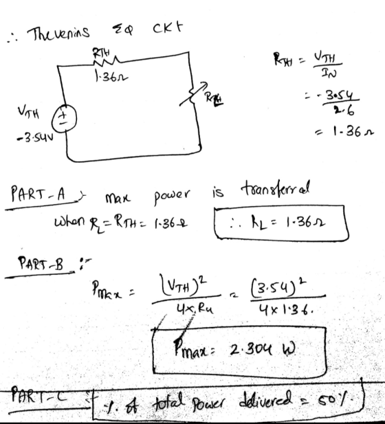
 Problem 4.87 The variable resistor (R.) in the circuit in (Figure 1) is adjusted until it absorbs maximum power from the circuit. Suppose that n = 5.0. Find the value of R. Express your answer to three significant figures and include the appropriate units. R. = Value Units Submit Request Answer Part B Find the maximum power delivered to Ro- Express your answer to three significant figures and include the appropriate units. Pmax = Value Units Submit Request Answer Figure...
 A variable resistor R is connected across the terminals a, b in the circuit in (Figure 1). The variable resistor is adjusted until maximum power is transferred to R, Suppose that Ug = 350 V and R = 13 kl. Part D 1.0 M 1.5 M Find the resistor from the table closest in value to the Ro Common Standard Resistor Values (12) 100 1.0 k 10 k 100 k 120 1.2 k 12 k 120k 1.5k 15 k 150...
 The variable resistor in the circuit in (Figure 1) is adjusted
for maximum power transfer to Ro. Suppose that ρ = 350.
Answer parts A-C please. Will thumb down if incorrect.
Express your answer to three significant figures and include the appropriate units. The variable resistor in the circuit in (Figure 1) is adjusted for maximum power transfer to R. Suppose that p= 350 R. = 43.0588 2 Submit Previous Answers Request Answer X Incorrect; Try Again; 9 attempts remaining...
The variable resistor in the circuit in (Figure 1) is adjusted
for maximum power transfer to Ro. Suppose that ρ = 350.
Answer parts A-C please. Will thumb down if incorrect.
Express your answer to three significant figures and include the appropriate units. The variable resistor in the circuit in (Figure 1) is adjusted for maximum power transfer to R. Suppose that p= 350 R. = 43.0588 2 Submit Previous Answers Request Answer X Incorrect; Try Again; 9 attempts remaining...
 Problem 4.90 PSpicelMultisim Part A The variable resistor (RL.) in the circuit in (Figure 1) is adjusted for maximum power transfer to RI. Suppose that R:54 Ω Find the numerical value of RL Express your answer to three significant figures and include the appropriate units RL-Value Units Submit vio Figure Incorrect; Try Again; 4 attempts remaining Part B 30 0 Find the maximum power transferred to RI Express your answer to three significant figures and include the appropriate units 45...
 I Review The figure below shows a resistive load R = 7 12 connected to a Thevenin equivalent circuit (Figure 1). Suppose that V = 36 V Part A For what value of Thevenin resistance is the power delivered to the load maximized? (Hint: Be careful; this is a tricky question if you don't stop to think about it.) Express your answer to two significant figures and include the appropriate units. ? .! HA Rs = Value O 2 Units...
 Problem 3.62 Use a Y-to-A transformation to find the unknown quantities for the circuit in (Figure 1). Suppose that , -8V Part A Find Express your answer to three significant figures and include the appropriate units. LA © ? Value Units Submit Request Answer Part B Findi Express your answer to three significant figures and include the appropriate units. HA O ? Value Units Submit Request Answer Part C Find 12 Express your answer to three significant figures and include...
 Problem 4.60 7 of 10 A Review Constants Consider the circuit shown in (Figure 1). Suppose that R.4k Part A Find the current in the circuit by making a succession of appropriate source transformations. Express your answer to three significant figures and include the appropriate units. 14,66 mA Previous Answers Figure 1 of 1 ✓ Correct Part B 40 kn 2:50 Work back through the circuit to find the magnitude of the power developed by the 120 V source Express...
 Problem 4.7 Consider the circuit shown in (Figure 1). The source voltage v1 is 40 V. Resistance R1, R2 and R3 are 5 ,120 and 15 , respectively. The source current I is 25 mA Part A Find the power developed by the current source I in the circuit. Express your answer to three significant figures and include the appropriate units. НА Value Units Рi 3 Request Answer Submit Part B Figure 1 of 1 Find the power developed by...
 \
Problem 6 Consider the circuit shown in (Figure 1). Suppose that V, = 480_0°V (rms). Part A Find the average power dissipated in the line in the figure Express your answer three significant figures and include the appropriate units. HHA ? P = Value Units Submit Request Answer Part B Figure 1 of 1 > Find the capacitive reactance that, when connected in parallel, with the load will make the load look purely resistive. Express your answer three significant...
\
Problem 6 Consider the circuit shown in (Figure 1). Suppose that V, = 480_0°V (rms). Part A Find the average power dissipated in the line in the figure Express your answer three significant figures and include the appropriate units. HHA ? P = Value Units Submit Request Answer Part B Figure 1 of 1 > Find the capacitive reactance that, when connected in parallel, with the load will make the load look purely resistive. Express your answer three significant...
 Problem 10.17 Constants The current I, in the frequency-domain circuit shown in (Figure 1) is 48 20° mA (rms). Figure 1 of 1 5() Ω j50 Ω 25 Ω eb923d80b761 180ae7361d64# 10001 s I Fall 18 Faisa art A ind the average power for the current source. Use positive value if the power is absorbed and negative value if the power is delivere Express your answer to three significant figures and include the appropriate units. P31993.675 W Submit X incorrect;...
Most questions answered within 3 hours.
-
The mean waiting time at the drive-through of a fast-food
restaurant from the time an order...
asked 6 minutes ago -
The pitch (p) of a helix is defined as p = dn, in which n is...
asked 8 minutes ago -
Do you agree that the declining stock of social capital is the
blame for the failure...
asked 11 minutes ago -
A researcher is interested in whether coffee consumption helps
with performance on reading comprehension tasks. The...
asked 21 minutes ago -
it has been estimated since the beginning of the human race that
about 133 metric ton...
asked 26 minutes ago -
Where must Medicare prescription drug plans allow for
participants to fill their prescriptions?
asked 30 minutes ago -
Five moles of monatomic ideal gas have initial pressure 2.50 ×
103 Pa and initial volume...
asked 44 minutes ago -
A resistor and the capacitor are used to control the timing in
the RC circuit of...
asked 44 minutes ago -
Living in a group could bring several disadvantages to an
individual. What are some of the...
asked 1 hour ago -
Complete and balance the following reactions. In case of no
reaction occurring write NR.
Mix #1:...
asked 1 hour ago -
If an economy consumes 75% of any increase in income, then an
increase in autonomous investment...
asked 1 hour ago -
A shotputter throws the shot with an initial speed of 15.8 m/s
at a 38.0 ∘...
asked 1 hour ago