

Homework Answers

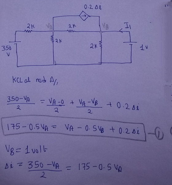

![10.200 2K km 2 13ko uth [VB = uth] KCL at node All 350 - VAZ VA-O + VA VB + 0.2 si 2. 175 -0.5VA - VA -0.5V8 + 0.2 (350,VA) 1](http://img.homeworklib.com/questions/7075c020-a16e-11eb-a301-efef7616ff2b.png?x-oss-process=image/resize,w_560)

Add Answer to:
A variable resistor R is connected across the terminals a, b in the circuit in (Figure...
Problem 4.87 The variable resistor (R.) in the circuit in (Figure 1) is adjusted until it...
 Problem 4.87 The variable resistor (R.) in the circuit in (Figure 1) is adjusted until it absorbs maximum power from the circuit. Suppose that n = 5.0. Find the value of R. Express your answer to three significant figures and include the appropriate units. R. = Value Units Submit Request Answer Part B Find the maximum power delivered to Ro- Express your answer to three significant figures and include the appropriate units. Pmax = Value Units Submit Request Answer Figure...
Problem 4.88 25 of 27 Review Constants The variable resistor (R) in the circuit in (Figure...
 Problem 4.88 25 of 27 Review Constants The variable resistor (R) in the circuit in (Figure 1) is adjusted until it absorbs maximum power from the circuit. Suppose that n = 7.5 Part A Find the value of R, Express your answer to three significant figures and include the appropriate units. HA Value Units Submi Request Answer Part B Find the maximum power delivered to R 1 of 1> Figure Express your answer to three significant figures and include the...
The variable resistor in the circuit in (Figure 1) is adjusted for maximum power transfer to...
 The variable resistor in the circuit in (Figure 1) is adjusted
for maximum power transfer to Ro. Suppose that ρ = 350.
Answer parts A-C please. Will thumb down if incorrect.
Express your answer to three significant figures and include the appropriate units. The variable resistor in the circuit in (Figure 1) is adjusted for maximum power transfer to R. Suppose that p= 350 R. = 43.0588 2 Submit Previous Answers Request Answer X Incorrect; Try Again; 9 attempts remaining...
The variable resistor in the circuit in (Figure 1) is adjusted
for maximum power transfer to Ro. Suppose that ρ = 350.
Answer parts A-C please. Will thumb down if incorrect.
Express your answer to three significant figures and include the appropriate units. The variable resistor in the circuit in (Figure 1) is adjusted for maximum power transfer to R. Suppose that p= 350 R. = 43.0588 2 Submit Previous Answers Request Answer X Incorrect; Try Again; 9 attempts remaining...
The variable resistor (R) in the circuit in (Figure 1) is adjusted for maximum power transfer...
 The variable resistor (R) in the circuit in (Figure 1) is adjusted for maximum power transfer to R. Suppose that P=256 X Incorrect; Try Again: 3 attempts remaining Part 6 Figure What percentage of the total power developed in the circuit is delivered to R, found in partA? Express your answer using three significant figures. 1 of 1 V AED vec RO? % delivered = 40 160 Submit Previous Answers Request Answer 400 V 180 C 200 V X Incorrect:...
please box all the answers for a thumbs up Problem 4.82 The variable resistor in the...
 please box all the answers for a thumbs up
Problem 4.82 The variable resistor in the circuit in (Figure 1) is adjusted for maximum power transfer to Ro. Suppose that R = 5 kl. Resistors (5% tolerance) [12] 10 100 1.0 k 10 k 100 k 1.0 M 120 1.2 k 12 k 120 k 15 150 1.5 k 15 k 150 k 1.5 M 180 1.8 k 18 k 180 k 22 220 2.2 k 22 k 220 k...
please box all the answers for a thumbs up
Problem 4.82 The variable resistor in the circuit in (Figure 1) is adjusted for maximum power transfer to Ro. Suppose that R = 5 kl. Resistors (5% tolerance) [12] 10 100 1.0 k 10 k 100 k 1.0 M 120 1.2 k 12 k 120 k 15 150 1.5 k 15 k 150 k 1.5 M 180 1.8 k 18 k 180 k 22 220 2.2 k 22 k 220 k...
Problem 4.90 PSpicelMultisim Part A The variable resistor (RL.) in the circuit in (Figure 1) is a...
 Problem 4.90 PSpicelMultisim Part A The variable resistor (RL.) in the circuit in (Figure 1) is adjusted for maximum power transfer to RI. Suppose that R:54 Ω Find the numerical value of RL Express your answer to three significant figures and include the appropriate units RL-Value Units Submit vio Figure Incorrect; Try Again; 4 attempts remaining Part B 30 0 Find the maximum power transferred to RI Express your answer to three significant figures and include the appropriate units 45...
In circuit A, a resistor of resistance R is connected across the terminals of a battery...
In circuit A, a resistor of resistance R is connected across the terminals of a battery with no internal resistance. In circuit B, an identical resistor is connected across a battery which is identical to the battery in the other circuit, except it has internal resistance r. 75.0% less power is dissipated in the resistor in circuit B than the resistor in circuit A. Determine the ratio r/R. Remember to express the answer with three significant digits.
Problem 1.20 The voltage and current at the terminals of the circuit element in the figure...
 Problem 1.20 The voltage and current at the terminals of the circuit element in the figure are zero for t < 0. Fort > Othey are v = 70e - 1600+ - 70e 400+ V. i = 6.0e 1600 - 6.0e 400mA. (Figure 1) Part A Find the power at t = 625 us. Express your answer to two significant figures and include the appropriate units. p= Value Units Submit Request Answer Figure < 1 of 1 > Part B...
Find the Norton equivalent with respect to the terminals a,b for the circuit in (Figure 1)...
 Find the Norton equivalent with respect to the terminals a,b for the circuit in (Figure 1) if v = 14 V, i = 6.5 A Find the equivalent current. Express your answer to three significant figures and include the appropriate units. ? μΑ Figure 1 of 1 Value Units IN= Request Answer Submit 12 0 2Ω a Part B Find the equivalent resistance. Express your answer to three significant figures and include the appropriate units.
Part A The voltage and current at the terminals of the circuit element in the figure...
 Part A The voltage and current at the terminals of the circuit element in the figure are zero for t0. For t0 they v75e-1600t i 7.0e-1600r 75e-00t v Find the power at t 650 AS Express your answer to two significant figures and include the appropriate units. 1600 7.0e-400mA. (Figure1 Value Units Submit Part B How much energy is delivered to the circuit element between 0 and 650 s? Express your answer to two significant figures and include the appropriate...
 Problem 4.87 The variable resistor (R.) in the circuit in (Figure 1) is adjusted until it absorbs maximum power from the circuit. Suppose that n = 5.0. Find the value of R. Express your answer to three significant figures and include the appropriate units. R. = Value Units Submit Request Answer Part B Find the maximum power delivered to Ro- Express your answer to three significant figures and include the appropriate units. Pmax = Value Units Submit Request Answer Figure...
 Problem 4.88 25 of 27 Review Constants The variable resistor (R) in the circuit in (Figure 1) is adjusted until it absorbs maximum power from the circuit. Suppose that n = 7.5 Part A Find the value of R, Express your answer to three significant figures and include the appropriate units. HA Value Units Submi Request Answer Part B Find the maximum power delivered to R 1 of 1> Figure Express your answer to three significant figures and include the...
 The variable resistor in the circuit in (Figure 1) is adjusted
for maximum power transfer to Ro. Suppose that ρ = 350.
Answer parts A-C please. Will thumb down if incorrect.
Express your answer to three significant figures and include the appropriate units. The variable resistor in the circuit in (Figure 1) is adjusted for maximum power transfer to R. Suppose that p= 350 R. = 43.0588 2 Submit Previous Answers Request Answer X Incorrect; Try Again; 9 attempts remaining...
The variable resistor in the circuit in (Figure 1) is adjusted
for maximum power transfer to Ro. Suppose that ρ = 350.
Answer parts A-C please. Will thumb down if incorrect.
Express your answer to three significant figures and include the appropriate units. The variable resistor in the circuit in (Figure 1) is adjusted for maximum power transfer to R. Suppose that p= 350 R. = 43.0588 2 Submit Previous Answers Request Answer X Incorrect; Try Again; 9 attempts remaining...
 The variable resistor (R) in the circuit in (Figure 1) is adjusted for maximum power transfer to R. Suppose that P=256 X Incorrect; Try Again: 3 attempts remaining Part 6 Figure What percentage of the total power developed in the circuit is delivered to R, found in partA? Express your answer using three significant figures. 1 of 1 V AED vec RO? % delivered = 40 160 Submit Previous Answers Request Answer 400 V 180 C 200 V X Incorrect:...
 please box all the answers for a thumbs up
Problem 4.82 The variable resistor in the circuit in (Figure 1) is adjusted for maximum power transfer to Ro. Suppose that R = 5 kl. Resistors (5% tolerance) [12] 10 100 1.0 k 10 k 100 k 1.0 M 120 1.2 k 12 k 120 k 15 150 1.5 k 15 k 150 k 1.5 M 180 1.8 k 18 k 180 k 22 220 2.2 k 22 k 220 k...
please box all the answers for a thumbs up
Problem 4.82 The variable resistor in the circuit in (Figure 1) is adjusted for maximum power transfer to Ro. Suppose that R = 5 kl. Resistors (5% tolerance) [12] 10 100 1.0 k 10 k 100 k 1.0 M 120 1.2 k 12 k 120 k 15 150 1.5 k 15 k 150 k 1.5 M 180 1.8 k 18 k 180 k 22 220 2.2 k 22 k 220 k...
 Problem 4.90 PSpicelMultisim Part A The variable resistor (RL.) in the circuit in (Figure 1) is adjusted for maximum power transfer to RI. Suppose that R:54 Ω Find the numerical value of RL Express your answer to three significant figures and include the appropriate units RL-Value Units Submit vio Figure Incorrect; Try Again; 4 attempts remaining Part B 30 0 Find the maximum power transferred to RI Express your answer to three significant figures and include the appropriate units 45...
 Problem 1.20 The voltage and current at the terminals of the circuit element in the figure are zero for t < 0. Fort > Othey are v = 70e - 1600+ - 70e 400+ V. i = 6.0e 1600 - 6.0e 400mA. (Figure 1) Part A Find the power at t = 625 us. Express your answer to two significant figures and include the appropriate units. p= Value Units Submit Request Answer Figure < 1 of 1 > Part B...
 Find the Norton equivalent with respect to the terminals a,b for the circuit in (Figure 1) if v = 14 V, i = 6.5 A Find the equivalent current. Express your answer to three significant figures and include the appropriate units. ? μΑ Figure 1 of 1 Value Units IN= Request Answer Submit 12 0 2Ω a Part B Find the equivalent resistance. Express your answer to three significant figures and include the appropriate units.
 Part A The voltage and current at the terminals of the circuit element in the figure are zero for t0. For t0 they v75e-1600t i 7.0e-1600r 75e-00t v Find the power at t 650 AS Express your answer to two significant figures and include the appropriate units. 1600 7.0e-400mA. (Figure1 Value Units Submit Part B How much energy is delivered to the circuit element between 0 and 650 s? Express your answer to two significant figures and include the appropriate...
Most questions answered within 3 hours.
-
Which of the following pairs of ions have the same electron
configuration?
I: Br− and Se2−...
asked 1 hour ago -
The Foremost Composite Materials Company is planning a two-day
sales conference for October 19-20. The conference...
asked 1 hour ago -
3) Illustrate the observed pattern of relatedness of organisms
versus adaptations to specific conditions. This means...
asked 2 hours ago -
In winter a lake has a 0.35 m thick ice layer over 1.10 m of
water....
asked 3 hours ago -
Assuming the following has been encrypted with a Vigenere cipher
below, use the method(s) and assumptions...
asked 3 hours ago -
How would I use switch statements to write a program that will
take an input of...
asked 3 hours ago -
Imagine a reaction in which methane gas combusts at a constant
pressure of 1 atm and...
asked 3 hours ago -
Two parallel wires (each 12 m in length) are separated by a
distance of 0.065 m...
asked 3 hours ago -
Suppose there were three masses at the corner of uniform
equilateral triangle. The masses are m1...
asked 3 hours ago -
Situation: A building that is 618 m above the ground floor. How
many times would a...
asked 3 hours ago -
help me and discuss one successful and one
unsuccessful international company/busines in Indonesia.whyit
succeed and why...
asked 3 hours ago -
I- Choose the best answer
Which of the following statements about the structure and
packaging of...
asked 3 hours ago