


please box all the answers for a thumbs up
Homework Answers


Add Answer to:
please box all the answers for a thumbs up
Problem 4.82 The variable resistor in the...
A variable resistor R is connected across the terminals a, b in the circuit in (Figure...
 A variable resistor R is connected across the terminals a, b in the circuit in (Figure 1). The variable resistor is adjusted until maximum power is transferred to R, Suppose that Ug = 350 V and R = 13 kl. Part D 1.0 M 1.5 M Find the resistor from the table closest in value to the Ro Common Standard Resistor Values (12) 100 1.0 k 10 k 100 k 120 1.2 k 12 k 120k 1.5k 15 k 150...
Resistor networks are sometimes used as volume-control circuits. In this application, they are re...
 Resistor networks are sometimes used as volume-control circuits.
In this application, they are referred to as resistance
attenuators or pads. A typical fixed-attenuator pad
is shown in the figure. In designing an attenuation pad, the
circuit designer will select the values of R1 and R2 so that the
ratio of vo/vi and the resistance seen by the input voltage source
Rabboth have a specified value. (Figure 1)
Resistors [Ω]
10
100
1.0 k
10 k
100 k
1.0 M
120...
Resistor networks are sometimes used as volume-control circuits.
In this application, they are referred to as resistance
attenuators or pads. A typical fixed-attenuator pad
is shown in the figure. In designing an attenuation pad, the
circuit designer will select the values of R1 and R2 so that the
ratio of vo/vi and the resistance seen by the input voltage source
Rabboth have a specified value. (Figure 1)
Resistors [Ω]
10
100
1.0 k
10 k
100 k
1.0 M
120...
Review | Constants Consider the circuit shown in (Figure 1). Suppose that vg 145 cos 10,000+...
 Review | Constants Consider the circuit shown in (Figure 1). Suppose that vg 145 cos 10,000+ V, where t is in seconds. = Part A Determine the load impedance for the circuit that will result in maximum average power being transferred to the load. Figure < 1 of 1 > Express your answer in ohms to three significant figures. Enter your answer in rectangular form. ► View Available Hint(s) 4 mH 2.5 F | ΑΣφ If vec ☺ ? 25...
Problem 4.87 The variable resistor (R.) in the circuit in (Figure 1) is adjusted until it...
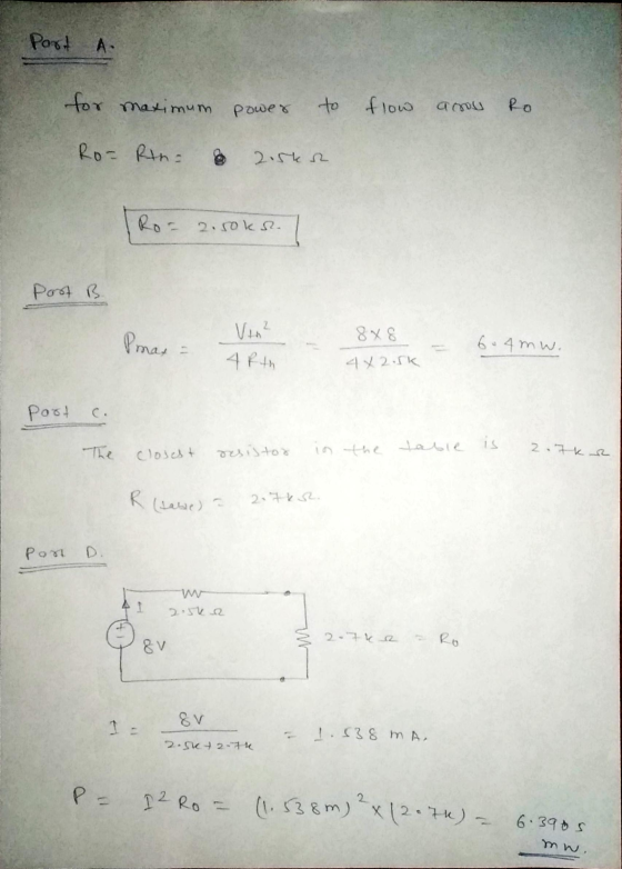
 Problem 4.87 The variable resistor (R.) in the circuit in (Figure 1) is adjusted until it absorbs maximum power from the circuit. Suppose that n = 5.0. Find the value of R. Express your answer to three significant figures and include the appropriate units. R. = Value Units Submit Request Answer Part B Find the maximum power delivered to Ro- Express your answer to three significant figures and include the appropriate units. Pmax = Value Units Submit Request Answer Figure...
Please box all answers for a thumbs up Consider the circuit shown in (Figure 1). Suppose...
 Please box all answers for a thumbs up
Consider the circuit shown in (Figure 1). Suppose that R = 7 kN. Figure K 1 of 1 Σ 40 ΚΩ 4 kΩ 2.5 kΩ 120 v 360 ΚΩ ()s.4 mA 390 kΩ 1.3 R 2 kΩ Part A Find the current i, in the circuit by making a succession of appropriate source transformations. Express your answer to three significant figures and include the appropriate units. μΑ ? io = Value mA...
Please box all answers for a thumbs up
Consider the circuit shown in (Figure 1). Suppose that R = 7 kN. Figure K 1 of 1 Σ 40 ΚΩ 4 kΩ 2.5 kΩ 120 v 360 ΚΩ ()s.4 mA 390 kΩ 1.3 R 2 kΩ Part A Find the current i, in the circuit by making a succession of appropriate source transformations. Express your answer to three significant figures and include the appropriate units. μΑ ? io = Value mA...
please box all answers for a thumbs up Problem 4.66 Find the Norton equivalent with respect...
 please box all answers for a thumbs up
Problem 4.66 Find the Norton equivalent with respect to the terminals a,b for the circuit in (Figure 1) if v = 20 V, i = 7 A. Figure 1 of 1 212 w V 2692 b Part A Find the equivalent current. Express your answer to three significant figures and include the appropriate units. HÅ ? IN = Value Units Submit Request Answer Part B Find the equivalent resistance. Express your answer...
please box all answers for a thumbs up
Problem 4.66 Find the Norton equivalent with respect to the terminals a,b for the circuit in (Figure 1) if v = 20 V, i = 7 A. Figure 1 of 1 212 w V 2692 b Part A Find the equivalent current. Express your answer to three significant figures and include the appropriate units. HÅ ? IN = Value Units Submit Request Answer Part B Find the equivalent resistance. Express your answer...
The variable resistor in the circuit in (Figure 1) is adjusted for maximum power transfer to...
 The variable resistor in the circuit in (Figure 1) is adjusted
for maximum power transfer to Ro. Suppose that ρ = 350.
Answer parts A-C please. Will thumb down if incorrect.
Express your answer to three significant figures and include the appropriate units. The variable resistor in the circuit in (Figure 1) is adjusted for maximum power transfer to R. Suppose that p= 350 R. = 43.0588 2 Submit Previous Answers Request Answer X Incorrect; Try Again; 9 attempts remaining...
The variable resistor in the circuit in (Figure 1) is adjusted
for maximum power transfer to Ro. Suppose that ρ = 350.
Answer parts A-C please. Will thumb down if incorrect.
Express your answer to three significant figures and include the appropriate units. The variable resistor in the circuit in (Figure 1) is adjusted for maximum power transfer to R. Suppose that p= 350 R. = 43.0588 2 Submit Previous Answers Request Answer X Incorrect; Try Again; 9 attempts remaining...
Problem 4.88 25 of 27 Review Constants The variable resistor (R) in the circuit in (Figure...
 Problem 4.88 25 of 27 Review Constants The variable resistor (R) in the circuit in (Figure 1) is adjusted until it absorbs maximum power from the circuit. Suppose that n = 7.5 Part A Find the value of R, Express your answer to three significant figures and include the appropriate units. HA Value Units Submi Request Answer Part B Find the maximum power delivered to R 1 of 1> Figure Express your answer to three significant figures and include the...
please box all answers Find the Norton equivalent with respect to the terminals a,b for the...
 please box all answers
Find the Norton equivalent with respect to the terminals a,b for the circuit seen in (Figure 1). Suppose that vg = 220 V and R = 5.0 k 2. Part A Find the equivalent current. Express your answer to three significant figures and include the appropriate units. μΑ in = Value Units Submit Request Answer Part B Figure 1 of 1 Find the equivalent resistance. Express your answer to three significant figures and include the appropriate...
please box all answers
Find the Norton equivalent with respect to the terminals a,b for the circuit seen in (Figure 1). Suppose that vg = 220 V and R = 5.0 k 2. Part A Find the equivalent current. Express your answer to three significant figures and include the appropriate units. μΑ in = Value Units Submit Request Answer Part B Figure 1 of 1 Find the equivalent resistance. Express your answer to three significant figures and include the appropriate...
Problem 4.90 PSpicelMultisim Part A The variable resistor (RL.) in the circuit in (Figure 1) is a...
 Problem 4.90 PSpicelMultisim Part A The variable resistor (RL.) in the circuit in (Figure 1) is adjusted for maximum power transfer to RI. Suppose that R:54 Ω Find the numerical value of RL Express your answer to three significant figures and include the appropriate units RL-Value Units Submit vio Figure Incorrect; Try Again; 4 attempts remaining Part B 30 0 Find the maximum power transferred to RI Express your answer to three significant figures and include the appropriate units 45...
 A variable resistor R is connected across the terminals a, b in the circuit in (Figure 1). The variable resistor is adjusted until maximum power is transferred to R, Suppose that Ug = 350 V and R = 13 kl. Part D 1.0 M 1.5 M Find the resistor from the table closest in value to the Ro Common Standard Resistor Values (12) 100 1.0 k 10 k 100 k 120 1.2 k 12 k 120k 1.5k 15 k 150...
 Resistor networks are sometimes used as volume-control circuits.
In this application, they are referred to as resistance
attenuators or pads. A typical fixed-attenuator pad
is shown in the figure. In designing an attenuation pad, the
circuit designer will select the values of R1 and R2 so that the
ratio of vo/vi and the resistance seen by the input voltage source
Rabboth have a specified value. (Figure 1)
Resistors [Ω]
10
100
1.0 k
10 k
100 k
1.0 M
120...
Resistor networks are sometimes used as volume-control circuits.
In this application, they are referred to as resistance
attenuators or pads. A typical fixed-attenuator pad
is shown in the figure. In designing an attenuation pad, the
circuit designer will select the values of R1 and R2 so that the
ratio of vo/vi and the resistance seen by the input voltage source
Rabboth have a specified value. (Figure 1)
Resistors [Ω]
10
100
1.0 k
10 k
100 k
1.0 M
120...
 Review | Constants Consider the circuit shown in (Figure 1). Suppose that vg 145 cos 10,000+ V, where t is in seconds. = Part A Determine the load impedance for the circuit that will result in maximum average power being transferred to the load. Figure < 1 of 1 > Express your answer in ohms to three significant figures. Enter your answer in rectangular form. ► View Available Hint(s) 4 mH 2.5 F | ΑΣφ If vec ☺ ? 25...
 Problem 4.87 The variable resistor (R.) in the circuit in (Figure 1) is adjusted until it absorbs maximum power from the circuit. Suppose that n = 5.0. Find the value of R. Express your answer to three significant figures and include the appropriate units. R. = Value Units Submit Request Answer Part B Find the maximum power delivered to Ro- Express your answer to three significant figures and include the appropriate units. Pmax = Value Units Submit Request Answer Figure...
 Please box all answers for a thumbs up
Consider the circuit shown in (Figure 1). Suppose that R = 7 kN. Figure K 1 of 1 Σ 40 ΚΩ 4 kΩ 2.5 kΩ 120 v 360 ΚΩ ()s.4 mA 390 kΩ 1.3 R 2 kΩ Part A Find the current i, in the circuit by making a succession of appropriate source transformations. Express your answer to three significant figures and include the appropriate units. μΑ ? io = Value mA...
Please box all answers for a thumbs up
Consider the circuit shown in (Figure 1). Suppose that R = 7 kN. Figure K 1 of 1 Σ 40 ΚΩ 4 kΩ 2.5 kΩ 120 v 360 ΚΩ ()s.4 mA 390 kΩ 1.3 R 2 kΩ Part A Find the current i, in the circuit by making a succession of appropriate source transformations. Express your answer to three significant figures and include the appropriate units. μΑ ? io = Value mA...
 please box all answers for a thumbs up
Problem 4.66 Find the Norton equivalent with respect to the terminals a,b for the circuit in (Figure 1) if v = 20 V, i = 7 A. Figure 1 of 1 212 w V 2692 b Part A Find the equivalent current. Express your answer to three significant figures and include the appropriate units. HÅ ? IN = Value Units Submit Request Answer Part B Find the equivalent resistance. Express your answer...
please box all answers for a thumbs up
Problem 4.66 Find the Norton equivalent with respect to the terminals a,b for the circuit in (Figure 1) if v = 20 V, i = 7 A. Figure 1 of 1 212 w V 2692 b Part A Find the equivalent current. Express your answer to three significant figures and include the appropriate units. HÅ ? IN = Value Units Submit Request Answer Part B Find the equivalent resistance. Express your answer...
 The variable resistor in the circuit in (Figure 1) is adjusted
for maximum power transfer to Ro. Suppose that ρ = 350.
Answer parts A-C please. Will thumb down if incorrect.
Express your answer to three significant figures and include the appropriate units. The variable resistor in the circuit in (Figure 1) is adjusted for maximum power transfer to R. Suppose that p= 350 R. = 43.0588 2 Submit Previous Answers Request Answer X Incorrect; Try Again; 9 attempts remaining...
The variable resistor in the circuit in (Figure 1) is adjusted
for maximum power transfer to Ro. Suppose that ρ = 350.
Answer parts A-C please. Will thumb down if incorrect.
Express your answer to three significant figures and include the appropriate units. The variable resistor in the circuit in (Figure 1) is adjusted for maximum power transfer to R. Suppose that p= 350 R. = 43.0588 2 Submit Previous Answers Request Answer X Incorrect; Try Again; 9 attempts remaining...
 Problem 4.88 25 of 27 Review Constants The variable resistor (R) in the circuit in (Figure 1) is adjusted until it absorbs maximum power from the circuit. Suppose that n = 7.5 Part A Find the value of R, Express your answer to three significant figures and include the appropriate units. HA Value Units Submi Request Answer Part B Find the maximum power delivered to R 1 of 1> Figure Express your answer to three significant figures and include the...
 please box all answers
Find the Norton equivalent with respect to the terminals a,b for the circuit seen in (Figure 1). Suppose that vg = 220 V and R = 5.0 k 2. Part A Find the equivalent current. Express your answer to three significant figures and include the appropriate units. μΑ in = Value Units Submit Request Answer Part B Figure 1 of 1 Find the equivalent resistance. Express your answer to three significant figures and include the appropriate...
please box all answers
Find the Norton equivalent with respect to the terminals a,b for the circuit seen in (Figure 1). Suppose that vg = 220 V and R = 5.0 k 2. Part A Find the equivalent current. Express your answer to three significant figures and include the appropriate units. μΑ in = Value Units Submit Request Answer Part B Figure 1 of 1 Find the equivalent resistance. Express your answer to three significant figures and include the appropriate...
 Problem 4.90 PSpicelMultisim Part A The variable resistor (RL.) in the circuit in (Figure 1) is adjusted for maximum power transfer to RI. Suppose that R:54 Ω Find the numerical value of RL Express your answer to three significant figures and include the appropriate units RL-Value Units Submit vio Figure Incorrect; Try Again; 4 attempts remaining Part B 30 0 Find the maximum power transferred to RI Express your answer to three significant figures and include the appropriate units 45...
Most questions answered within 3 hours.
-
Explain in detail
Germany is the fifth largest economy
explain what goods and services Germany specializes...
asked 9 minutes ago -
The density of platinum is 21.45 g/mL. If a cube of platinum
with a mass of...
asked 14 minutes ago -
Accounts Receivable
Sales
A/R Posting
Extended Sales Invoice
Packing Slip
Compare invoice to packing slip 2...
asked 17 minutes ago -
Michaella, age 23, is a full-time law student and is claimed by
her parents as a...
asked 18 minutes ago -
Why are polymers not typically casted into products?
asked 35 minutes ago -
When rolling a die 129 times, what is the probability of rolling
a 6 no more...
asked 52 minutes ago -
4. A call option currently sells for $7.75. It has a strike
price of $85 and...
asked 40 minutes ago -
1.
You need to prepare 10.0 liters of an acid aqueous solution with a
pH of...
asked 43 minutes ago -
Along an aggregate supply curve, if the level of output is less
than the natural level...
asked 44 minutes ago -
By 2025, annual consumption in emerging markets will total $30
trillion and contribute more than ________...
asked 49 minutes ago -
At what point does reformation cease to be a viable option for
those who are oppressed...
asked 53 minutes ago -
Place letters corresponding to amounts in the proper order for
lightest to heaviest samples:
a) 2100...
asked 57 minutes ago