Resistor networks are sometimes used as volume-control circuits.
In this application, they are referred to as resistance
attenuators or pads. A typical fixed-attenuator pad
is shown in the figure. In designing an attenuation pad, the
circuit designer will select the values of R1 and R2 so that the
ratio of vo/vi and the resistance seen by the input voltage source
Rabboth have a specified value. (Figure 1)
| Resistors [Ω] | |||||
| 10 | 100 | 1.0 k | 10 k | 100 k | 1.0 M |
| 120 | 1.2 k | 12 k | 120 k | ||
| 15 | 150 | 1.5 k | 15 k | 150 k | 1.5 M |
| 180 | 1.8 k | 18 k | 180 k | ||
| 22 | 220 | 2.2 k | 22 k | 220 k | 2.2 M |
| 270 | 2.7 k | 27 k | 270 k | ||
| 33 | 330 | 3.3 k | 33 k | 330 k | 3.3 M |
| 390 | 3.9 k | 39 k | 390 k | ||
| 47 | 470 | 4.7 k | 47 k | 470 k | 4.7 M |
| 560 | 5.6 k | 56 k | 560 k | ||
| 68 | 680 | 6.8 k | 68 k | 680 k | 6.8 M |
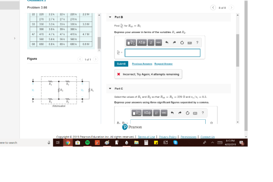


22 220 2.2k 22k 220k 2.2 M Part C 270 2.7 k 27k270 k Select the values of R1 and R2 so that Rab-RL-270 Ω and Vo/Vi-0.5 Express your answers using three significant figures separated by a comma 33 330 3.3 k 33 k 330 k3.3 M 390 3.9 k39 k390 k 47 470 4.7k47 470k4.7 M 560 5.6k56 k 560 k 6.8 M 68 680 6.8 k 68 k 680k n2 Figure
Homework Answers


Add Answer to:
Resistor networks are sometimes used as volume-control circuits. In this application, they are re...
Review | Constants Consider the circuit shown in (Figure 1). Suppose that vg 145 cos 10,000+...
 Review | Constants Consider the circuit shown in (Figure 1). Suppose that vg 145 cos 10,000+ V, where t is in seconds. = Part A Determine the load impedance for the circuit that will result in maximum average power being transferred to the load. Figure < 1 of 1 > Express your answer in ohms to three significant figures. Enter your answer in rectangular form. ► View Available Hint(s) 4 mH 2.5 F | ΑΣφ If vec ☺ ? 25...
please box all the answers for a thumbs up Problem 4.82 The variable resistor in the...
 please box all the answers for a thumbs up
Problem 4.82 The variable resistor in the circuit in (Figure 1) is adjusted for maximum power transfer to Ro. Suppose that R = 5 kl. Resistors (5% tolerance) [12] 10 100 1.0 k 10 k 100 k 1.0 M 120 1.2 k 12 k 120 k 15 150 1.5 k 15 k 150 k 1.5 M 180 1.8 k 18 k 180 k 22 220 2.2 k 22 k 220 k...
please box all the answers for a thumbs up
Problem 4.82 The variable resistor in the circuit in (Figure 1) is adjusted for maximum power transfer to Ro. Suppose that R = 5 kl. Resistors (5% tolerance) [12] 10 100 1.0 k 10 k 100 k 1.0 M 120 1.2 k 12 k 120 k 15 150 1.5 k 15 k 150 k 1.5 M 180 1.8 k 18 k 180 k 22 220 2.2 k 22 k 220 k...
A variable resistor R is connected across the terminals a, b in the circuit in (Figure...
 A variable resistor R is connected across the terminals a, b in the circuit in (Figure 1). The variable resistor is adjusted until maximum power is transferred to R, Suppose that Ug = 350 V and R = 13 kl. Part D 1.0 M 1.5 M Find the resistor from the table closest in value to the Ro Common Standard Resistor Values (12) 100 1.0 k 10 k 100 k 120 1.2 k 12 k 120k 1.5k 15 k 150...
Please design a clipper circuit that produces voltage as shown. You may the standard value pf...
 Please design a clipper circuit that produces voltage as
shown. You may the standard value pf resistor as guidlines
ASSIGNMENT BEE2213 19201 QUESTION 2 Design a clipper circuit that produces voltage output as shown in the Figure 1. Vi 15V N ? Vi Vo Vo 5V Figure 1 @ 43% .. MY MAXIS 4G 14:38 Done Assignment_Guideline_2130afeo... 2 RSG FREE BEE2213/192011 APPENDIX 1- Standard Value Resistors Standard Values of Commercially Available Resistors Ohms (0) Kilo Ohms (KO) Mega Ohms (MO)...
Please design a clipper circuit that produces voltage as
shown. You may the standard value pf resistor as guidlines
ASSIGNMENT BEE2213 19201 QUESTION 2 Design a clipper circuit that produces voltage output as shown in the Figure 1. Vi 15V N ? Vi Vo Vo 5V Figure 1 @ 43% .. MY MAXIS 4G 14:38 Done Assignment_Guideline_2130afeo... 2 RSG FREE BEE2213/192011 APPENDIX 1- Standard Value Resistors Standard Values of Commercially Available Resistors Ohms (0) Kilo Ohms (KO) Mega Ohms (MO)...
Problem 7 Re Consider the circuit shown in (Figure 1). Suppose that va = 130 cos...
 Problem 7 Re Consider the circuit shown in (Figure 1). Suppose that va = 130 cos 10,000+ V, where is in seconds. Part A Determine the load impedance for the circuit that will result in maximum average power being transferred to the load. Express your answer in ohms to three significant figures. Enter your answer in rectangular form. View Available Hints) 21 = 20.0 20.00 22 Previous Answers Correct Here we learn how to find the impedance of the circuit...
Solve each practice problem. TYPE solutions in engineering notation TYPE solutions in engineering notation. Calcula...
 Solve each practice problem. TYPE solutions in
engineering notation
TYPE solutions in engineering
notation.
Calculate the component voltages and branch currents for the circuit shown in Figure 6.40, along with the values of I, and Rr. 3. R3 2 kn R4 4.7 k R1 10 k Vs 26 V R5 3.3 k R2 3 kn FIGURE 6.40 Calculate the component currents and loop voltages for the circuit shown in Figure 6.42, along with the values of I and Rr 5....
Solve each practice problem. TYPE solutions in
engineering notation
TYPE solutions in engineering
notation.
Calculate the component voltages and branch currents for the circuit shown in Figure 6.40, along with the values of I, and Rr. 3. R3 2 kn R4 4.7 k R1 10 k Vs 26 V R5 3.3 k R2 3 kn FIGURE 6.40 Calculate the component currents and loop voltages for the circuit shown in Figure 6.42, along with the values of I and Rr 5....
Design a current divider/shunt resistance that will allow a lmA (full scale) 140 2 (internal resistance)...
 Design a current divider/shunt resistance that will allow a lmA (full scale) 140 2 (internal resistance) d'Arsonval meter to measure 10mA at full scale (i.e. iunknown 10 mA, imeter 1 mA, Rmeter 140 , Rshunt?). NOTE: You may need to use up to two standard resistor values in series and/or parallel combinations to reach the needed shunt resistance. Lab values are: 10 22, 33, 47, 56, 68, 82, 100, 220, 330, 470, 560, 680, 820, lk, 2.2k, ..., IM2 Calculate...
Can somone show me how to do the 1st problem? Need to find the LS and...
 Can somone show me how to do the 1st problem? Need to
find the LS and SS for the fit and the LH and SH for the hole.
Fits are all SHAFT BASIS METRIC but the shaft and hole diameters can not be used right out of the table. This is because the 3mm shaft tolerance does not match. You will need to lookup the "Fit" from the table, and then use the LS (Largest Shaft) and SS (Smallest Shaft)...
Can somone show me how to do the 1st problem? Need to
find the LS and SS for the fit and the LH and SH for the hole.
Fits are all SHAFT BASIS METRIC but the shaft and hole diameters can not be used right out of the table. This is because the 3mm shaft tolerance does not match. You will need to lookup the "Fit" from the table, and then use the LS (Largest Shaft) and SS (Smallest Shaft)...
 Review | Constants Consider the circuit shown in (Figure 1). Suppose that vg 145 cos 10,000+ V, where t is in seconds. = Part A Determine the load impedance for the circuit that will result in maximum average power being transferred to the load. Figure < 1 of 1 > Express your answer in ohms to three significant figures. Enter your answer in rectangular form. ► View Available Hint(s) 4 mH 2.5 F | ΑΣφ If vec ☺ ? 25...
 please box all the answers for a thumbs up
Problem 4.82 The variable resistor in the circuit in (Figure 1) is adjusted for maximum power transfer to Ro. Suppose that R = 5 kl. Resistors (5% tolerance) [12] 10 100 1.0 k 10 k 100 k 1.0 M 120 1.2 k 12 k 120 k 15 150 1.5 k 15 k 150 k 1.5 M 180 1.8 k 18 k 180 k 22 220 2.2 k 22 k 220 k...
please box all the answers for a thumbs up
Problem 4.82 The variable resistor in the circuit in (Figure 1) is adjusted for maximum power transfer to Ro. Suppose that R = 5 kl. Resistors (5% tolerance) [12] 10 100 1.0 k 10 k 100 k 1.0 M 120 1.2 k 12 k 120 k 15 150 1.5 k 15 k 150 k 1.5 M 180 1.8 k 18 k 180 k 22 220 2.2 k 22 k 220 k...
 A variable resistor R is connected across the terminals a, b in the circuit in (Figure 1). The variable resistor is adjusted until maximum power is transferred to R, Suppose that Ug = 350 V and R = 13 kl. Part D 1.0 M 1.5 M Find the resistor from the table closest in value to the Ro Common Standard Resistor Values (12) 100 1.0 k 10 k 100 k 120 1.2 k 12 k 120k 1.5k 15 k 150...
 Please design a clipper circuit that produces voltage as
shown. You may the standard value pf resistor as guidlines
ASSIGNMENT BEE2213 19201 QUESTION 2 Design a clipper circuit that produces voltage output as shown in the Figure 1. Vi 15V N ? Vi Vo Vo 5V Figure 1 @ 43% .. MY MAXIS 4G 14:38 Done Assignment_Guideline_2130afeo... 2 RSG FREE BEE2213/192011 APPENDIX 1- Standard Value Resistors Standard Values of Commercially Available Resistors Ohms (0) Kilo Ohms (KO) Mega Ohms (MO)...
Please design a clipper circuit that produces voltage as
shown. You may the standard value pf resistor as guidlines
ASSIGNMENT BEE2213 19201 QUESTION 2 Design a clipper circuit that produces voltage output as shown in the Figure 1. Vi 15V N ? Vi Vo Vo 5V Figure 1 @ 43% .. MY MAXIS 4G 14:38 Done Assignment_Guideline_2130afeo... 2 RSG FREE BEE2213/192011 APPENDIX 1- Standard Value Resistors Standard Values of Commercially Available Resistors Ohms (0) Kilo Ohms (KO) Mega Ohms (MO)...
 Problem 7 Re Consider the circuit shown in (Figure 1). Suppose that va = 130 cos 10,000+ V, where is in seconds. Part A Determine the load impedance for the circuit that will result in maximum average power being transferred to the load. Express your answer in ohms to three significant figures. Enter your answer in rectangular form. View Available Hints) 21 = 20.0 20.00 22 Previous Answers Correct Here we learn how to find the impedance of the circuit...
 Solve each practice problem. TYPE solutions in
engineering notation
TYPE solutions in engineering
notation.
Calculate the component voltages and branch currents for the circuit shown in Figure 6.40, along with the values of I, and Rr. 3. R3 2 kn R4 4.7 k R1 10 k Vs 26 V R5 3.3 k R2 3 kn FIGURE 6.40 Calculate the component currents and loop voltages for the circuit shown in Figure 6.42, along with the values of I and Rr 5....
Solve each practice problem. TYPE solutions in
engineering notation
TYPE solutions in engineering
notation.
Calculate the component voltages and branch currents for the circuit shown in Figure 6.40, along with the values of I, and Rr. 3. R3 2 kn R4 4.7 k R1 10 k Vs 26 V R5 3.3 k R2 3 kn FIGURE 6.40 Calculate the component currents and loop voltages for the circuit shown in Figure 6.42, along with the values of I and Rr 5....
 Design a current divider/shunt resistance that will allow a lmA (full scale) 140 2 (internal resistance) d'Arsonval meter to measure 10mA at full scale (i.e. iunknown 10 mA, imeter 1 mA, Rmeter 140 , Rshunt?). NOTE: You may need to use up to two standard resistor values in series and/or parallel combinations to reach the needed shunt resistance. Lab values are: 10 22, 33, 47, 56, 68, 82, 100, 220, 330, 470, 560, 680, 820, lk, 2.2k, ..., IM2 Calculate...
 Can somone show me how to do the 1st problem? Need to
find the LS and SS for the fit and the LH and SH for the hole.
Fits are all SHAFT BASIS METRIC but the shaft and hole diameters can not be used right out of the table. This is because the 3mm shaft tolerance does not match. You will need to lookup the "Fit" from the table, and then use the LS (Largest Shaft) and SS (Smallest Shaft)...
Can somone show me how to do the 1st problem? Need to
find the LS and SS for the fit and the LH and SH for the hole.
Fits are all SHAFT BASIS METRIC but the shaft and hole diameters can not be used right out of the table. This is because the 3mm shaft tolerance does not match. You will need to lookup the "Fit" from the table, and then use the LS (Largest Shaft) and SS (Smallest Shaft)...
Most questions answered within 3 hours.
-
Explain in detail
Germany is the fifth largest economy
explain what goods and services Germany specializes...
asked 6 minutes ago -
The density of platinum is 21.45 g/mL. If a cube of platinum
with a mass of...
asked 11 minutes ago -
Accounts Receivable
Sales
A/R Posting
Extended Sales Invoice
Packing Slip
Compare invoice to packing slip 2...
asked 14 minutes ago -
Michaella, age 23, is a full-time law student and is claimed by
her parents as a...
asked 14 minutes ago -
Why are polymers not typically casted into products?
asked 31 minutes ago -
When rolling a die 129 times, what is the probability of rolling
a 6 no more...
asked 48 minutes ago -
4. A call option currently sells for $7.75. It has a strike
price of $85 and...
asked 37 minutes ago -
1.
You need to prepare 10.0 liters of an acid aqueous solution with a
pH of...
asked 40 minutes ago -
Along an aggregate supply curve, if the level of output is less
than the natural level...
asked 40 minutes ago -
By 2025, annual consumption in emerging markets will total $30
trillion and contribute more than ________...
asked 45 minutes ago -
At what point does reformation cease to be a viable option for
those who are oppressed...
asked 49 minutes ago -
Place letters corresponding to amounts in the proper order for
lightest to heaviest samples:
a) 2100...
asked 54 minutes ago