Please explain how to get angle for neutral axis and find
highest tensile stress not compression
Homework Answers


Add Answer to:
Please explain how to get angle for neutral axis and find
highest tensile stress not compression...
3) (40 pts) The EXTERNAL 35 kN force P is applied to the end of a 2 m long cantilever beam with t...
 3) (40 pts) The EXTERNAL 35 kN force P is applied to the end of a 2 m long cantilever beam with the given cross section. The force acts through the shear center, forming an angle of 35 with the horizontal axis. The x, y axes pass through the centroid C. The y-axis can be assumed to coincide with the right- hand edge of the vertical section. Determine (a) the normal bending stress at Point A, (b) normal bending stress...
1. A steel angle has a cross-section as indicated. Find the horizontal neutral axis (N.A.) and...
 1. A steel angle has a cross-section as indicated. Find the
horizontal neutral axis (N.A.) and moment of inertia (I) for the
indicated shape.
2. The steel angle from problem 1 is used as a beam to span 8.5
feet. A heavy mechanical pipe is suspended from the beam at
midspan. The load from the pipe is 2,350 lbs.
a) Draw a free body diagram for the beam, and
determine the reactions at each end of the beam.
b) The...
1. A steel angle has a cross-section as indicated. Find the
horizontal neutral axis (N.A.) and moment of inertia (I) for the
indicated shape.
2. The steel angle from problem 1 is used as a beam to span 8.5
feet. A heavy mechanical pipe is suspended from the beam at
midspan. The load from the pipe is 2,350 lbs.
a) Draw a free body diagram for the beam, and
determine the reactions at each end of the beam.
b) The...
Q1. A 2 m long T-beam is built-in at one end and has a force of...
 Q1. A 2 m long T-beam is built-in at one end and has a force of 7 kN applied at its free end. The dimensions of the cross-section of the beam are shown in Fig. Q1 and the force acts at 10° to the vertical though the centroid of the section. 7 KN 1 -10° 251 -y 100 1 44 32 44 all dimensions in mm Fig. Q1 - Cross-sectional Dimensions of T-beam (a) Find the position of the centroid...
Question 4: (25 marks) A hollow rectangular cross-section (Figure 4) is subject to the combined effect...
 Question 4: (25 marks) A hollow rectangular cross-section (Figure 4) is subject to the combined effect of A torque T (causing downward shear stress in the right wall and upward shear stress in the left wall): T= 60 kNm. A negative bending moment M about the horizontal centroidal x-axis (causing tension in the top part of the cross-section): M= 100 kNm. Given t 15 mm: i. Determine the maximum tensile stress at A on the x-axis on the left wall...
Review Learning Goal: To use the superposition principle to find the state of stress on a...
 Review Learning Goal: To use the superposition principle to find the state of stress on a beam under multiple loadings The beam shown below is subjected to a horizontal force P via the rope wound around the pulley. The state of stress at point A is to be determined. Part A - Support Reactions and Internal Loading Determine the support reactions Cy and Cz and the internal normal force, shear force, and moment on the cross-section containing point A. Express...
3-34 For each section illustrated, find the second moment of area, the location of the neutral...
 3-34 For each section illustrated, find the second moment of area, the location of the neutral axis, and the distances from the neutral axis to the top and bottom surfaces. Consider that the section is transmitting a positive bending moment about the z axis, M., where M. = 10 kipin if the dimen- sions of the section are given in ips units, or M. = 1.13 kNm if the dimensions are in SI units. Determine the resulting stresses at the...
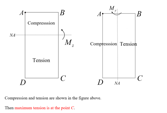
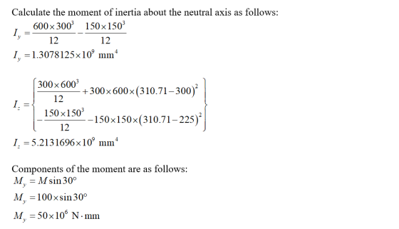
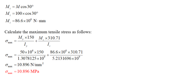
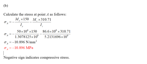
3) (35 pts) A L-beam has the cross section shown. A moment M acts about the...
 3) (35 pts) A L-beam has the cross section shown. A moment M acts about the x-axis which passes through the centroid of the section. Determine the angle the neutral axis makes with respect to the +x- axis. Sketch it on the cross section. Given the design flexural stress limit is 100 MPa, determine the maximum allowable moment which can be applied. You only need to evaluate the stresses at points A, 8. Helpful hint: Remember to change the sign...
3) (35 pts) A L-beam has the cross section shown. A moment M acts about the...
 3) (35 pts) A L-beam has the cross section shown. A moment M acts about the x-axis which passes through the centroid of the section. Determine the angle the neutral axis makes with respect to axis. Sketch it on the cross section. Given the design flexural stress limit is 100 MPa, determine the maximum allowable moment which can be applied. You only need to evaluate the stresses at points A, B. Helpful hint: Remember to change the sign of your...
For each section illustrated, find the second moment of area, the location of the neutral axis,...
 For each section illustrated, find the second moment of area, the location of the neutral axis, and the distances from the neutral axis to the top and bottom surfaces. Consider that the section is transmitting a positive bending moment about the z axis, M, where M. 1.13 kN m. Determine the resulting stresses at the top and bottom surfaces and at every abrupt change in the cross section. om 6 mm 25 mim 25 1mm Ca) 3y 100 ー75 12.5...
 3) (40 pts) The EXTERNAL 35 kN force P is applied to the end of a 2 m long cantilever beam with the given cross section. The force acts through the shear center, forming an angle of 35 with the horizontal axis. The x, y axes pass through the centroid C. The y-axis can be assumed to coincide with the right- hand edge of the vertical section. Determine (a) the normal bending stress at Point A, (b) normal bending stress...
 1. A steel angle has a cross-section as indicated. Find the
horizontal neutral axis (N.A.) and moment of inertia (I) for the
indicated shape.
2. The steel angle from problem 1 is used as a beam to span 8.5
feet. A heavy mechanical pipe is suspended from the beam at
midspan. The load from the pipe is 2,350 lbs.
a) Draw a free body diagram for the beam, and
determine the reactions at each end of the beam.
b) The...
1. A steel angle has a cross-section as indicated. Find the
horizontal neutral axis (N.A.) and moment of inertia (I) for the
indicated shape.
2. The steel angle from problem 1 is used as a beam to span 8.5
feet. A heavy mechanical pipe is suspended from the beam at
midspan. The load from the pipe is 2,350 lbs.
a) Draw a free body diagram for the beam, and
determine the reactions at each end of the beam.
b) The...
 Q1. A 2 m long T-beam is built-in at one end and has a force of 7 kN applied at its free end. The dimensions of the cross-section of the beam are shown in Fig. Q1 and the force acts at 10° to the vertical though the centroid of the section. 7 KN 1 -10° 251 -y 100 1 44 32 44 all dimensions in mm Fig. Q1 - Cross-sectional Dimensions of T-beam (a) Find the position of the centroid...
 Question 4: (25 marks) A hollow rectangular cross-section (Figure 4) is subject to the combined effect of A torque T (causing downward shear stress in the right wall and upward shear stress in the left wall): T= 60 kNm. A negative bending moment M about the horizontal centroidal x-axis (causing tension in the top part of the cross-section): M= 100 kNm. Given t 15 mm: i. Determine the maximum tensile stress at A on the x-axis on the left wall...
 Question 4: (25 marks) A hollow rectangular cross-section (Figure 4) is subject to the combined effect of A torque T (causing downward shear stress in the right wall and upward shear stress in the left wall): T= 60 kNm. A negative bending moment M about the horizontal centroidal x-axis (causing tension in the top part of the cross-section): M= 100 kNm. Given t 15 mm: i. Determine the maximum tensile stress at A on the x-axis on the left wall...
 Review Learning Goal: To use the superposition principle to find the state of stress on a beam under multiple loadings The beam shown below is subjected to a horizontal force P via the rope wound around the pulley. The state of stress at point A is to be determined. Part A - Support Reactions and Internal Loading Determine the support reactions Cy and Cz and the internal normal force, shear force, and moment on the cross-section containing point A. Express...
 3-34 For each section illustrated, find the second moment of area, the location of the neutral axis, and the distances from the neutral axis to the top and bottom surfaces. Consider that the section is transmitting a positive bending moment about the z axis, M., where M. = 10 kipin if the dimen- sions of the section are given in ips units, or M. = 1.13 kNm if the dimensions are in SI units. Determine the resulting stresses at the...
 3) (35 pts) A L-beam has the cross section shown. A moment M acts about the x-axis which passes through the centroid of the section. Determine the angle the neutral axis makes with respect to the +x- axis. Sketch it on the cross section. Given the design flexural stress limit is 100 MPa, determine the maximum allowable moment which can be applied. You only need to evaluate the stresses at points A, 8. Helpful hint: Remember to change the sign...
 3) (35 pts) A L-beam has the cross section shown. A moment M acts about the x-axis which passes through the centroid of the section. Determine the angle the neutral axis makes with respect to axis. Sketch it on the cross section. Given the design flexural stress limit is 100 MPa, determine the maximum allowable moment which can be applied. You only need to evaluate the stresses at points A, B. Helpful hint: Remember to change the sign of your...
 For each section illustrated, find the second moment of area, the location of the neutral axis, and the distances from the neutral axis to the top and bottom surfaces. Consider that the section is transmitting a positive bending moment about the z axis, M, where M. 1.13 kN m. Determine the resulting stresses at the top and bottom surfaces and at every abrupt change in the cross section. om 6 mm 25 mim 25 1mm Ca) 3y 100 ー75 12.5...
Most questions answered within 3 hours.
-
4. Without doing any calculations, predict whether the observed
∆T would increase, decrease or remain the...
asked 6 minutes ago -
Based on the range, which of the following sets of scores has
the greatest variability? 3,...
asked 1 hour ago -
Ripples in a pond travel at a velocity of 3 m/s with one peak
passing a...
asked 1 hour ago -
A man stands on the roof of a building of height 13.0 mm and
throws a...
asked 1 hour ago -
The extent to which assets are financed by borrowed funds and
other liabilities is indicated by:...
asked 2 hours ago -
Explain in detail
Germany is the fifth largest economy
explain what goods and services Germany specializes...
asked 2 hours ago -
The density of platinum is 21.45 g/mL. If a cube of platinum
with a mass of...
asked 2 hours ago -
Accounts Receivable
Sales
A/R Posting
Extended Sales Invoice
Packing Slip
Compare invoice to packing slip 2...
asked 2 hours ago -
Michaella, age 23, is a full-time law student and is claimed by
her parents as a...
asked 2 hours ago -
Why are polymers not typically casted into products?
asked 2 hours ago -
When rolling a die 129 times, what is the probability of rolling
a 6 no more...
asked 3 hours ago -
4. A call option currently sells for $7.75. It has a strike
price of $85 and...
asked 2 hours ago