

Homework Answers


Add Answer to:
Review Learning Goal: To use the superposition principle to find the state of stress on a...
Learning Goal: To use the superposition principle to find the state of stress on a beam...
 Learning Goal: To use the superposition principle to find the state of stress on a beam under multiple loadings. The beam shown below is subjected to a horizontal force P via the rope wound around the pulley. The state of stress at point A is to be determined. P 1d4 di dz d2 20 mm T 100 mm 200 mm 15 mm 20 mm 150 mm The dimensions are di = 1.85 m, d2 = 0.5 m, dz = 0.9...
Part A - Support Reactions and Internal Loading Learning Goal: To use the superposition principle to...
 Part A - Support Reactions and Internal Loading Learning Goal: To use the superposition principle to find the state of stress on a beam under multiple loadings. The beam shown below is subjected to a horizontal force P via the rope wound around the pulley. The state of stress at point A is to be determined Determine the support reactions Cy and Cand the internal normal force, shear force, and moment on the cross-section containing point A Express your answers,...
Part A - Support Reactions and Internal Loading Learning Goal: To use the superposition principle to...
 Part A - Support Reactions and Internal Loading Learning Goal: To use the superposition principle to find the state stress on a bear under multiple loadings. The beam shown below is subjected to a horizontal force P via the rope wound around the pulley. The state of stress at point A is to be determined Determine the support reactions, and C, and the intemal normal force, shear force, and moment on the cross-section containing point A. Express your answers, separated...
Learning Goal: To determine the state of stress in a solid rod using the principle of...
 Learning Goal: To determine the state of stress in a solid rod using the principle of superposition. A solid rod has a diameter of e = 55 mm and is subjected to the loading shown. Let a = 190 mm, b = 220 mm , c = 350 mm, d = 240 mm , and P = 4.0 kN. Take point A to be at the top of the circular cross-section. (Figure 1) Figure < 1 of 2 b В...
Part A - Moment about the x axis at A Learning Goal: To determine the state...
 Part A - Moment about the x axis at A Learning Goal: To determine the state of stress in a solid rod using the principle of superposition. A solid rod has a diameter of e = 60 mm and is subjected to the loading shown. Let a = 200 mm, b = 220 mm c = 340 mm, d = 230 mm, and P = 4.0 kN. Take point A to be at the top of the circular cross-section. (Figure...
u Review Part B - Calculate the moment of inertia Learning Goal: To find the centroid...
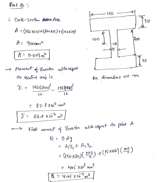
 u Review Part B - Calculate the moment of inertia Learning Goal: To find the centroid and moment of inertia of an I-beam's cross section, and to use the flexure formula to find the stress at a point on the cross section due to an internal bending moment. Once the position of the centroid is known, the moment of inertia can be calculated. What is the moment of inertia of the section for bending around the z-axis? Express your answer...
Learning Goal: To use the principle of superposition to determine the total deflection in a cylindrical...
 Learning Goal: To use the principle of superposition to determine the total deflection in a cylindrical rod due to a static loading. A steel rod (E= 200 GPa) is subjected to the load shown, where P = 2800 kN. A gap a = 1.90 mm exists before the load is applied. The elongated rod contacts the top surface at C'. Assume the mass of the rod is negligible. The values for the figure below are d = 0.900 m, e...
Learning Goal: To calculate the normal and shear stresses at a point on the cross section...
 Learning Goal: To calculate the normal and shear stresses at a point on the cross section of a column. The state of stress at a point is a description of the normal and shear stresses at that point. The normal stresses are generally due to both internal normal force and internal bending moment. The net result can be obtained using the principle of superposition as long as the deflections remain small and the response is elastic. Figure < 1 of...
Learning Goal: To calculate torsional deformation and shear stress due to an applied force in a...
 Learning Goal: To calculate torsional deformation and shear stress due to an applied force in a door handle design. A locked door handle is composed of a solid circular shaft AB with a diameter fb = 105 mm and a flat plate BC with a force P = 76 N applied at point C as shown. Let c = 543 mm, d = 125 mm, and e = 145 mm. (Treat the handle as if it were a cantilever beam.)...
Learning Goal: To calculate torsional deformation and shear stress due to an applied force in a...
 Learning Goal: To calculate torsional deformation and shear stress due to an applied force in a door handle design. A locked door handle is composed of a solid circular shaft AB with a diameter of b = 101 mm and a flat plate BC with a force P = 77 N applied at point C as shown. Let c = 473 mm, d = 126 mm, and e = 148 mm (Treat the handle as if it were a cantilever...
 Learning Goal: To use the superposition principle to find the state of stress on a beam under multiple loadings. The beam shown below is subjected to a horizontal force P via the rope wound around the pulley. The state of stress at point A is to be determined. P 1d4 di dz d2 20 mm T 100 mm 200 mm 15 mm 20 mm 150 mm The dimensions are di = 1.85 m, d2 = 0.5 m, dz = 0.9...
 Part A - Support Reactions and Internal Loading Learning Goal: To use the superposition principle to find the state of stress on a beam under multiple loadings. The beam shown below is subjected to a horizontal force P via the rope wound around the pulley. The state of stress at point A is to be determined Determine the support reactions Cy and Cand the internal normal force, shear force, and moment on the cross-section containing point A Express your answers,...
 Part A - Support Reactions and Internal Loading Learning Goal: To use the superposition principle to find the state stress on a bear under multiple loadings. The beam shown below is subjected to a horizontal force P via the rope wound around the pulley. The state of stress at point A is to be determined Determine the support reactions, and C, and the intemal normal force, shear force, and moment on the cross-section containing point A. Express your answers, separated...
 Learning Goal: To determine the state of stress in a solid rod using the principle of superposition. A solid rod has a diameter of e = 55 mm and is subjected to the loading shown. Let a = 190 mm, b = 220 mm , c = 350 mm, d = 240 mm , and P = 4.0 kN. Take point A to be at the top of the circular cross-section. (Figure 1) Figure < 1 of 2 b В...
 Part A - Moment about the x axis at A Learning Goal: To determine the state of stress in a solid rod using the principle of superposition. A solid rod has a diameter of e = 60 mm and is subjected to the loading shown. Let a = 200 mm, b = 220 mm c = 340 mm, d = 230 mm, and P = 4.0 kN. Take point A to be at the top of the circular cross-section. (Figure...
 u Review Part B - Calculate the moment of inertia Learning Goal: To find the centroid and moment of inertia of an I-beam's cross section, and to use the flexure formula to find the stress at a point on the cross section due to an internal bending moment. Once the position of the centroid is known, the moment of inertia can be calculated. What is the moment of inertia of the section for bending around the z-axis? Express your answer...
 Learning Goal: To use the principle of superposition to determine the total deflection in a cylindrical rod due to a static loading. A steel rod (E= 200 GPa) is subjected to the load shown, where P = 2800 kN. A gap a = 1.90 mm exists before the load is applied. The elongated rod contacts the top surface at C'. Assume the mass of the rod is negligible. The values for the figure below are d = 0.900 m, e...
 Learning Goal: To calculate the normal and shear stresses at a point on the cross section of a column. The state of stress at a point is a description of the normal and shear stresses at that point. The normal stresses are generally due to both internal normal force and internal bending moment. The net result can be obtained using the principle of superposition as long as the deflections remain small and the response is elastic. Figure < 1 of...
 Learning Goal: To calculate torsional deformation and shear stress due to an applied force in a door handle design. A locked door handle is composed of a solid circular shaft AB with a diameter fb = 105 mm and a flat plate BC with a force P = 76 N applied at point C as shown. Let c = 543 mm, d = 125 mm, and e = 145 mm. (Treat the handle as if it were a cantilever beam.)...
 Learning Goal: To calculate torsional deformation and shear stress due to an applied force in a door handle design. A locked door handle is composed of a solid circular shaft AB with a diameter of b = 101 mm and a flat plate BC with a force P = 77 N applied at point C as shown. Let c = 473 mm, d = 126 mm, and e = 148 mm (Treat the handle as if it were a cantilever...
Most questions answered within 3 hours.
-
Which types of mutations in DNA can lead to the translation of a
non-functional protein product?...
asked 1 minute from now -
Many structures are composed of individual elements that react
in unison when forces are applied. the...
asked 5 seconds ago -
Work of 1950 J is done by stirring a perfectly insulated beaker
containing 75 g of...
asked 29 minutes ago -
The neighborhood kids set up an outdoor lemonade stand in
Maryland in June. They find that...
asked 31 minutes ago -
9. A company has a beginning inventory of 4,000 units. The
company estimates it will sell...
asked 44 minutes ago -
A patient goes to the doctor's office with symptoms of a urinary
tract infection and provides...
asked 47 minutes ago -
When responding to the essay questions, be sure to cite any
material you obtained from a...
asked 47 minutes ago -
The energy of an electron in a 2.25-eV-deep potential well is
1.50 eV.At what distance into...
asked 48 minutes ago -
Q1:Which three evolutionary innovations are present in land
plants (but not all land plants) that allowed...
asked 51 minutes ago -
Lymphosarcoma is
extremely rare. Risk factors for the disease are largely unknown.
What kind of study...
asked 54 minutes ago -
The solubility of benzoic acid in water is:
0.29g/100mL at 20°C
6.8g/100mL at 100°C
a) What...
asked 55 minutes ago -
Which food law was passed in 1996 and changed how pesticide
residues on food were regulated...
asked 1 hour ago