


Homework Answers
![To 10o 4 * 200 K 15min toot + 200x15 x 150mm X B) A= 2x150x20) + 9000 mm2 9x10³ m2 I= 150X2403_ (150–15] x 2003 = 82.8x106mmy](http://img.homeworklib.com/questions/040fefd0-dee8-11ea-a556-79337c919dda.png?x-oss-process=image/resize,w_560)
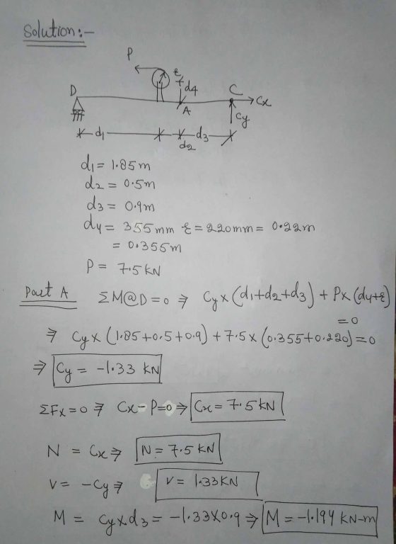
In N , Cy= -133 N, V= 133N
Add Answer to:
Learning Goal: To use the superposition principle to find the state of stress on a beam...
Review Learning Goal: To use the superposition principle to find the state of stress on a...
 Review Learning Goal: To use the superposition principle to find the state of stress on a beam under multiple loadings The beam shown below is subjected to a horizontal force P via the rope wound around the pulley. The state of stress at point A is to be determined. Part A - Support Reactions and Internal Loading Determine the support reactions Cy and Cz and the internal normal force, shear force, and moment on the cross-section containing point A. Express...
Part A - Support Reactions and Internal Loading Learning Goal: To use the superposition principle to...
 Part A - Support Reactions and Internal Loading Learning Goal: To use the superposition principle to find the state of stress on a beam under multiple loadings. The beam shown below is subjected to a horizontal force P via the rope wound around the pulley. The state of stress at point A is to be determined Determine the support reactions Cy and Cand the internal normal force, shear force, and moment on the cross-section containing point A Express your answers,...
Part A - Support Reactions and Internal Loading Learning Goal: To use the superposition principle to...
 Part A - Support Reactions and Internal Loading Learning Goal: To use the superposition principle to find the state stress on a bear under multiple loadings. The beam shown below is subjected to a horizontal force P via the rope wound around the pulley. The state of stress at point A is to be determined Determine the support reactions, and C, and the intemal normal force, shear force, and moment on the cross-section containing point A. Express your answers, separated...
Learning Goal: To determine the state of stress in a solid rod using the principle of...
 Learning Goal: To determine the state of stress in a solid rod using the principle of superposition. A solid rod has a diameter of e = 55 mm and is subjected to the loading shown. Let a = 190 mm, b = 220 mm , c = 350 mm, d = 240 mm , and P = 4.0 kN. Take point A to be at the top of the circular cross-section. (Figure 1) Figure < 1 of 2 b В...
Learning Goal: The beam shown (Figure 1) is supported by a pin at A and a...
 Learning Goal: The beam shown (Figure 1) is supported by a pin at A and a cable at B. Two loads P = 18 kN are applied straight down from the centerline of the bottom face. Determine the state of stress at the point shown (Figure 2) in a section 2 m from the wall. The dimensions are w = 5.4 cm , h = 12 cm, L = 0.8 m, a = 1.5 cm , and b = 4...
Learning Goal: To calculate the shear stress at the web/flange joint in a beam and use...
 Learning Goal: To calculate the shear stress at the web/flange joint in a beam and use that stress to calculate the required nail spacing to make a built- up beam. A built up beam can be constructed by fastening flat plates together. When an l-beam is subjected to a shear load, internal shear stress is developed at every cross section, with longitudinal shear stress balancing transverse shear stress. If the beam is built up using plates, the fasteners used must...
Leaming Goal: To determine the shear stresses at specific locations in a beam due to an...
 Leaming Goal: To determine the shear stresses at specific locations in a beam due to an external loading. Beam ABC is subjected to the loading shown, where PB = 40.0 kN. The measurement corresponding to the half-length of the beam is a = 2.50 m. For the cross section shown, b = 50.0 mm, c= 125.0 mm, d = 125.0 mm, and e = 65.0 mm Point Dis located at the centroid of the cross section and point E is...
Learning Goal: To calculate torsional deformation and shear stress due to an applied force in a...
 Learning Goal: To calculate torsional deformation and shear stress due to an applied force in a door handle design. A locked door handle is composed of a solid circular shaft AB with a diameter fb = 105 mm and a flat plate BC with a force P = 76 N applied at point C as shown. Let c = 543 mm, d = 125 mm, and e = 145 mm. (Treat the handle as if it were a cantilever beam.)...
Part A - Moment about the x axis at A Learning Goal: To determine the state...
 Part A - Moment about the x axis at A Learning Goal: To determine the state of stress in a solid rod using the principle of superposition. A solid rod has a diameter of e = 60 mm and is subjected to the loading shown. Let a = 200 mm, b = 220 mm c = 340 mm, d = 230 mm, and P = 4.0 kN. Take point A to be at the top of the circular cross-section. (Figure...
Learning Goal: To calculate the normal and shear stresses at a point on the cross section...
 Learning Goal: To calculate the normal and shear stresses at a point on the cross section of a column. The state of stress at a point is a description of the normal and shear stresses at that point. The normal stresses are generally due to both internal normal force and internal bending moment. The net result can be obtained using the principle of superposition as long as the deflections remain small and the response is elastic. Figure < 1 of...
 Review Learning Goal: To use the superposition principle to find the state of stress on a beam under multiple loadings The beam shown below is subjected to a horizontal force P via the rope wound around the pulley. The state of stress at point A is to be determined. Part A - Support Reactions and Internal Loading Determine the support reactions Cy and Cz and the internal normal force, shear force, and moment on the cross-section containing point A. Express...
 Part A - Support Reactions and Internal Loading Learning Goal: To use the superposition principle to find the state of stress on a beam under multiple loadings. The beam shown below is subjected to a horizontal force P via the rope wound around the pulley. The state of stress at point A is to be determined Determine the support reactions Cy and Cand the internal normal force, shear force, and moment on the cross-section containing point A Express your answers,...
 Part A - Support Reactions and Internal Loading Learning Goal: To use the superposition principle to find the state stress on a bear under multiple loadings. The beam shown below is subjected to a horizontal force P via the rope wound around the pulley. The state of stress at point A is to be determined Determine the support reactions, and C, and the intemal normal force, shear force, and moment on the cross-section containing point A. Express your answers, separated...
 Learning Goal: To determine the state of stress in a solid rod using the principle of superposition. A solid rod has a diameter of e = 55 mm and is subjected to the loading shown. Let a = 190 mm, b = 220 mm , c = 350 mm, d = 240 mm , and P = 4.0 kN. Take point A to be at the top of the circular cross-section. (Figure 1) Figure < 1 of 2 b В...
 Learning Goal: The beam shown (Figure 1) is supported by a pin at A and a cable at B. Two loads P = 18 kN are applied straight down from the centerline of the bottom face. Determine the state of stress at the point shown (Figure 2) in a section 2 m from the wall. The dimensions are w = 5.4 cm , h = 12 cm, L = 0.8 m, a = 1.5 cm , and b = 4...
 Learning Goal: To calculate the shear stress at the web/flange joint in a beam and use that stress to calculate the required nail spacing to make a built- up beam. A built up beam can be constructed by fastening flat plates together. When an l-beam is subjected to a shear load, internal shear stress is developed at every cross section, with longitudinal shear stress balancing transverse shear stress. If the beam is built up using plates, the fasteners used must...
 Leaming Goal: To determine the shear stresses at specific locations in a beam due to an external loading. Beam ABC is subjected to the loading shown, where PB = 40.0 kN. The measurement corresponding to the half-length of the beam is a = 2.50 m. For the cross section shown, b = 50.0 mm, c= 125.0 mm, d = 125.0 mm, and e = 65.0 mm Point Dis located at the centroid of the cross section and point E is...
 Learning Goal: To calculate torsional deformation and shear stress due to an applied force in a door handle design. A locked door handle is composed of a solid circular shaft AB with a diameter fb = 105 mm and a flat plate BC with a force P = 76 N applied at point C as shown. Let c = 543 mm, d = 125 mm, and e = 145 mm. (Treat the handle as if it were a cantilever beam.)...
 Part A - Moment about the x axis at A Learning Goal: To determine the state of stress in a solid rod using the principle of superposition. A solid rod has a diameter of e = 60 mm and is subjected to the loading shown. Let a = 200 mm, b = 220 mm c = 340 mm, d = 230 mm, and P = 4.0 kN. Take point A to be at the top of the circular cross-section. (Figure...
 Learning Goal: To calculate the normal and shear stresses at a point on the cross section of a column. The state of stress at a point is a description of the normal and shear stresses at that point. The normal stresses are generally due to both internal normal force and internal bending moment. The net result can be obtained using the principle of superposition as long as the deflections remain small and the response is elastic. Figure < 1 of...
Most questions answered within 3 hours.
-
The activation energy for a given reaction is 50.3 kJ/mol. If
the rate constant for the...
asked 5 minutes ago -
An entomologist discovers a dung beetle rolling a ball of dung
along the ground, and decides...
asked 1 hour ago -
Humans have used horses for transportation for millions of
years. Therefore, they will use horses for...
asked 3 hours ago -
The following are the Jensen Corporation's unit costs of making
and selling an item at a...
asked 4 hours ago -
Does direct Medicare reimbursement of Advanced practice nurses
increase access to their services?
asked 5 hours ago -
List and explain why a company would choose to use a
published
compensation survey vs. creating...
asked 5 hours ago -
A discrete random variable X can take values from 1 to 10. Find
the variance of...
asked 5 hours ago -
The primary financial goal of a corporation is to maximize:
shareholders wealth.
earnings per share.
stock...
asked 5 hours ago -
determine whether the vectors u=(1,2,3,), v=(-2,1,0) and
w=(1,0,1) are linearly dependent or independent.
asked 5 hours ago -
python
Define a function called print_values which takes a dictionary
object as a parameter. The function...
asked 6 hours ago -
In Chapter 1 you created a program named Triangle in
which you displayed a seven-line triangle...
asked 6 hours ago -
Research question: What are the differences between separately
stated and non separately stated transactions in an...
asked 7 hours ago