

Homework Answers


Add Answer to:
Part A - Support Reactions and Internal Loading Learning Goal: To use the superposition principle to...
Part A - Support Reactions and Internal Loading Learning Goal: To use the superposition principle to...
 Part A - Support Reactions and Internal Loading Learning Goal: To use the superposition principle to find the state of stress on a beam under multiple loadings. The beam shown below is subjected to a horizontal force P via the rope wound around the pulley. The state of stress at point A is to be determined Determine the support reactions Cy and Cand the internal normal force, shear force, and moment on the cross-section containing point A Express your answers,...
Review Learning Goal: To use the superposition principle to find the state of stress on a...
 Review Learning Goal: To use the superposition principle to find the state of stress on a beam under multiple loadings The beam shown below is subjected to a horizontal force P via the rope wound around the pulley. The state of stress at point A is to be determined. Part A - Support Reactions and Internal Loading Determine the support reactions Cy and Cz and the internal normal force, shear force, and moment on the cross-section containing point A. Express...
Learning Goal: To use the superposition principle to find the state of stress on a beam...
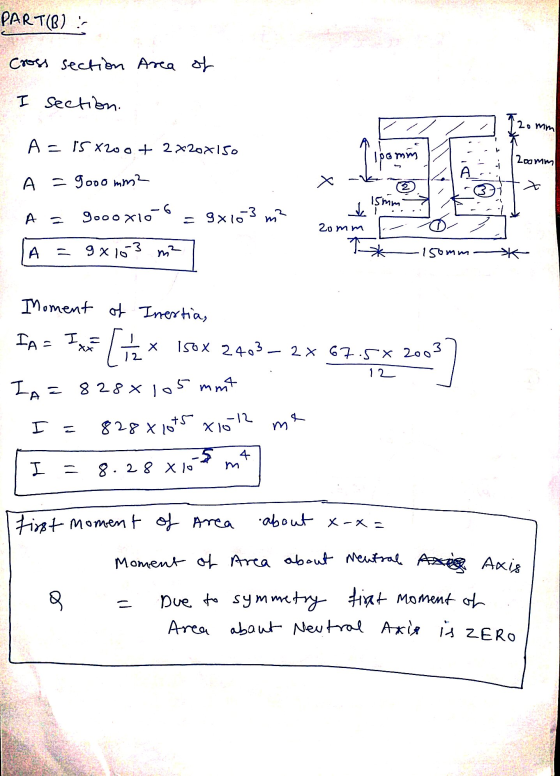
 Learning Goal: To use the superposition principle to find the state of stress on a beam under multiple loadings. The beam shown below is subjected to a horizontal force P via the rope wound around the pulley. The state of stress at point A is to be determined. P 1d4 di dz d2 20 mm T 100 mm 200 mm 15 mm 20 mm 150 mm The dimensions are di = 1.85 m, d2 = 0.5 m, dz = 0.9...
Learning Goal: To calculate the normal and shear stresses at a point on the cross section...
 Learning Goal: To calculate the normal and shear stresses at a point on the cross section of a column. The state of stress at a point is a description of the normal and shear stresses at that point. The normal stresses are generally due to both internal normal force and internal bending moment. The net result can be obtained using the principle of superposition as long as the deflections remain small and the response is elastic. Figure < 1 of...
Learning Goal: The beam shown (Figure 1) is supported by a pin at A and a...
 Learning Goal: The beam shown (Figure 1) is supported by a pin at A and a cable at B. Two loads P = 18 kN are applied straight down from the centerline of the bottom face. Determine the state of stress at the point shown (Figure 2) in a section 2 m from the wall. The dimensions are w = 5.4 cm , h = 12 cm, L = 0.8 m, a = 1.5 cm , and b = 4...
Learning Goal: To determine the state of stress in a solid rod using the principle of...
 Learning Goal: To determine the state of stress in a solid rod using the principle of superposition. A solid rod has a diameter of e = 55 mm and is subjected to the loading shown. Let a = 190 mm, b = 220 mm , c = 350 mm, d = 240 mm , and P = 4.0 kN. Take point A to be at the top of the circular cross-section. (Figure 1) Figure < 1 of 2 b В...
Part A - Moment about the x axis at A Learning Goal: To determine the state...
 Part A - Moment about the x axis at A Learning Goal: To determine the state of stress in a solid rod using the principle of superposition. A solid rod has a diameter of e = 60 mm and is subjected to the loading shown. Let a = 200 mm, b = 220 mm c = 340 mm, d = 230 mm, and P = 4.0 kN. Take point A to be at the top of the circular cross-section. (Figure...
Torsional Deformation of a Circular Shaft Learning Goal: To calculate torsional deformation and s...
 Torsional Deformation of a Circular Shaft Learning Goal: To calculate torsional deformation and shear stress due to an applied force in a door handle design. A locked door handle is composed of a solid orcular shaft AB with a diameter of b 101 mm and a flat plate BC with a ferce P-65 N applied at point C as shown Let c 523 mm,d 135 mm, and e 157 mm (Treat the hande as if it were a cantilever beam)...
Leaming Goal: To determine the shear stresses at specific locations in a beam due to an...
 Leaming Goal: To determine the shear stresses at specific locations in a beam due to an external loading. Beam ABC is subjected to the loading shown, where PB = 40.0 kN. The measurement corresponding to the half-length of the beam is a = 2.50 m. For the cross section shown, b = 50.0 mm, c= 125.0 mm, d = 125.0 mm, and e = 65.0 mm Point Dis located at the centroid of the cross section and point E is...
Learning Goal: To calculate torsional deformation and shear stress due to an applied force in a...
 Learning Goal: To calculate torsional deformation and shear stress due to an applied force in a door handle design. A locked door handle is composed of a solid circular shaft AB with a diameter fb = 105 mm and a flat plate BC with a force P = 76 N applied at point C as shown. Let c = 543 mm, d = 125 mm, and e = 145 mm. (Treat the handle as if it were a cantilever beam.)...
 Part A - Support Reactions and Internal Loading Learning Goal: To use the superposition principle to find the state of stress on a beam under multiple loadings. The beam shown below is subjected to a horizontal force P via the rope wound around the pulley. The state of stress at point A is to be determined Determine the support reactions Cy and Cand the internal normal force, shear force, and moment on the cross-section containing point A Express your answers,...
 Review Learning Goal: To use the superposition principle to find the state of stress on a beam under multiple loadings The beam shown below is subjected to a horizontal force P via the rope wound around the pulley. The state of stress at point A is to be determined. Part A - Support Reactions and Internal Loading Determine the support reactions Cy and Cz and the internal normal force, shear force, and moment on the cross-section containing point A. Express...
 Learning Goal: To use the superposition principle to find the state of stress on a beam under multiple loadings. The beam shown below is subjected to a horizontal force P via the rope wound around the pulley. The state of stress at point A is to be determined. P 1d4 di dz d2 20 mm T 100 mm 200 mm 15 mm 20 mm 150 mm The dimensions are di = 1.85 m, d2 = 0.5 m, dz = 0.9...
 Learning Goal: To calculate the normal and shear stresses at a point on the cross section of a column. The state of stress at a point is a description of the normal and shear stresses at that point. The normal stresses are generally due to both internal normal force and internal bending moment. The net result can be obtained using the principle of superposition as long as the deflections remain small and the response is elastic. Figure < 1 of...
 Learning Goal: The beam shown (Figure 1) is supported by a pin at A and a cable at B. Two loads P = 18 kN are applied straight down from the centerline of the bottom face. Determine the state of stress at the point shown (Figure 2) in a section 2 m from the wall. The dimensions are w = 5.4 cm , h = 12 cm, L = 0.8 m, a = 1.5 cm , and b = 4...
 Learning Goal: To determine the state of stress in a solid rod using the principle of superposition. A solid rod has a diameter of e = 55 mm and is subjected to the loading shown. Let a = 190 mm, b = 220 mm , c = 350 mm, d = 240 mm , and P = 4.0 kN. Take point A to be at the top of the circular cross-section. (Figure 1) Figure < 1 of 2 b В...
 Part A - Moment about the x axis at A Learning Goal: To determine the state of stress in a solid rod using the principle of superposition. A solid rod has a diameter of e = 60 mm and is subjected to the loading shown. Let a = 200 mm, b = 220 mm c = 340 mm, d = 230 mm, and P = 4.0 kN. Take point A to be at the top of the circular cross-section. (Figure...
 Torsional Deformation of a Circular Shaft Learning Goal: To calculate torsional deformation and shear stress due to an applied force in a door handle design. A locked door handle is composed of a solid orcular shaft AB with a diameter of b 101 mm and a flat plate BC with a ferce P-65 N applied at point C as shown Let c 523 mm,d 135 mm, and e 157 mm (Treat the hande as if it were a cantilever beam)...
 Leaming Goal: To determine the shear stresses at specific locations in a beam due to an external loading. Beam ABC is subjected to the loading shown, where PB = 40.0 kN. The measurement corresponding to the half-length of the beam is a = 2.50 m. For the cross section shown, b = 50.0 mm, c= 125.0 mm, d = 125.0 mm, and e = 65.0 mm Point Dis located at the centroid of the cross section and point E is...
 Learning Goal: To calculate torsional deformation and shear stress due to an applied force in a door handle design. A locked door handle is composed of a solid circular shaft AB with a diameter fb = 105 mm and a flat plate BC with a force P = 76 N applied at point C as shown. Let c = 543 mm, d = 125 mm, and e = 145 mm. (Treat the handle as if it were a cantilever beam.)...
Most questions answered within 3 hours.
-
Write the net ionic equation for the precipitation reaction that
occurs when aqueous solutions of potassium...
asked 4 minutes ago -
it
should be written in c++
Your program should take numbers from the user until the...
asked 10 minutes ago -
Buses are powered by chemical reactions. Define matter and the
four states of matter. What is...
asked 27 minutes ago -
Use conservation of energy to find the velocity of a free point
charge q1 at 22cm...
asked 35 minutes ago -
First, describe policies promoted by governments of the
political right to address economic globalization. Second, describe...
asked 52 minutes ago -
M2-9 Completing T-Accounts LO2-4
Following are the transactions of Dennen, Inc., for the month of
January....
asked 52 minutes ago -
Write a program using python that reads from values from a text
file and plots them...
asked 53 minutes ago -
Look up the density of
the metal of the object used in parts A and B...
asked 52 minutes ago -
Discuss strategic considerations that Amazon and NYC politicians
had. Analyze why the deal between Amazon and...
asked 56 minutes ago -
A combustion reaction is describes as a carbon source reacting
with oxygen and producing carbon dioxide...
asked 1 hour ago -
Buckminsterfullerence is a recently allotrope of carbon in which
carbon atoms form molecules of formula C_60,...
asked 1 hour ago -
Lower Equitorial and Upper Equitorial are the same except Lower
Equitorial has a larger capital stock....
asked 1 hour ago