


Homework Answers
Add Answer to:
Learning Goal: To calculate torsional deformation and shear stress due to an applied force in a...
Learning Goal: To calculate torsional deformation and shear stress due to an applied force in a...
 Learning Goal: To calculate torsional deformation and shear stress due to an applied force in a door handle design. A locked door handle is composed of a solid circular shaft AB with a diameter fb = 105 mm and a flat plate BC with a force P = 76 N applied at point C as shown. Let c = 543 mm, d = 125 mm, and e = 145 mm. (Treat the handle as if it were a cantilever beam.)...
Learning Goal: To calculate torsional deformation and shear stress due to an applied force in a...
 Learning Goal: To calculate torsional deformation and shear stress due to an applied force in a door handle design. A locked door handle is composed of a solid circular shaft AB with a diameter of b = 101 mm and a flat plate BC with a force P = 77 N applied at point C as shown. Let c = 473 mm, d = 126 mm, and e = 148 mm (Treat the handle as if it were a cantilever...
Torsional Deformation of a Circular Shaft Learning Goal: To calculate torsional deformation and s...
 Torsional Deformation of a Circular Shaft Learning Goal: To calculate torsional deformation and shear stress due to an applied force in a door handle design. A locked door handle is composed of a solid orcular shaft AB with a diameter of b 101 mm and a flat plate BC with a ferce P-65 N applied at point C as shown Let c 523 mm,d 135 mm, and e 157 mm (Treat the hande as if it were a cantilever beam)...
Learning Goal: To determine the maximum shear force that can be applied to two shafts of...
 Learning Goal: To determine the maximum shear force that can be applied to two shafts of varying cross sections: a solid square shaft and a hollow square shaft. The two square cross sections shown below (Figure 1) are each subjected to a vertical shear force, V. The side length of each cross section is s = 6.00 in and the side length of the hollowed- out portion of the second cross section is r = 2.25 in. The maximum allowable...
Homework 4 porsional Deformation of a Circular Shaft Learning Goal locacao sinal de and shared to...
 Homework 4 porsional Deformation of a Circular Shaft Learning Goal locacao sinal de and shared to anaped for en a Aloed door handles composed of scrush Al Wadiameter ndere 100 mandate with a force P.14 Naleport as shown Leemed 12mmande 15m (hte handie s e werbe Part A Mano Shermocon. mon d by the Express the shear stress to the significatures and include appropriate unit View Available Type here to search A D 18 PM 1125/2019 14 ° 5 °6...
Learning Goal: To calculate the normal and shear stresses at a point on the cross section...
 Learning Goal: To calculate the normal and shear stresses at a point on the cross section of a column. The state of stress at a point is a description of the normal and shear stresses at that point. The normal stresses are generally due to both internal normal force and internal bending moment. The net result can be obtained using the principle of superposition as long as the deflections remain small and the response is elastic. Figure < 1 of...
Learning Goal: To calculate the shear stress at the web/flange joint in a beam and use...
 Learning Goal: To calculate the shear stress at the web/flange joint in a beam and use that stress to calculate the required nail spacing to make a built- up beam. A built up beam can be constructed by fastening flat plates together. When an l-beam is subjected to a shear load, internal shear stress is developed at every cross section, with longitudinal shear stress balancing transverse shear stress. If the beam is built up using plates, the fasteners used must...
Learning Goal: To determine the state of stress in a solid rod using the principle of...
 Learning Goal: To determine the state of stress in a solid rod using the principle of superposition. A solid rod has a diameter of e = 55 mm and is subjected to the loading shown. Let a = 190 mm, b = 220 mm , c = 350 mm, d = 240 mm , and P = 4.0 kN. Take point A to be at the top of the circular cross-section. (Figure 1) Figure < 1 of 2 b В...
Learning Goal: To determine the angle of twist on a composite rod given the geometry and...
 Learning Goal: To determine the angle of twist on a composite rod given the geometry and externally applied torques, to properly apply a sign convention to determine the angle of twist, to use a torque diagram to aid in determining the angle of twist, and to determine the maximum applicable torque given a maximum allowable angle of twist. The rod shown below is made of two different materials. Segment AB is made of aluminum (G=27 GPa). Segment BC is bonded...
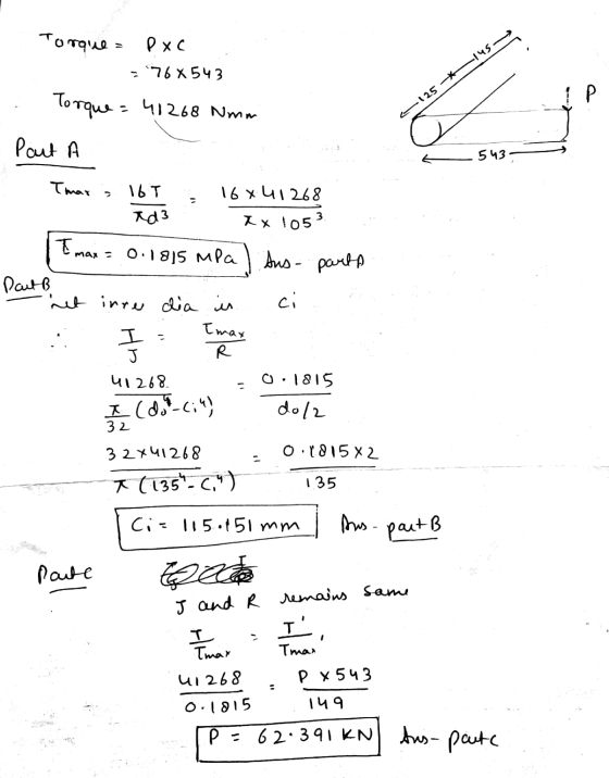
 Learning Goal: To calculate torsional deformation and shear stress due to an applied force in a door handle design. A locked door handle is composed of a solid circular shaft AB with a diameter fb = 105 mm and a flat plate BC with a force P = 76 N applied at point C as shown. Let c = 543 mm, d = 125 mm, and e = 145 mm. (Treat the handle as if it were a cantilever beam.)...
 Learning Goal: To calculate torsional deformation and shear stress due to an applied force in a door handle design. A locked door handle is composed of a solid circular shaft AB with a diameter of b = 101 mm and a flat plate BC with a force P = 77 N applied at point C as shown. Let c = 473 mm, d = 126 mm, and e = 148 mm (Treat the handle as if it were a cantilever...
 Torsional Deformation of a Circular Shaft Learning Goal: To calculate torsional deformation and shear stress due to an applied force in a door handle design. A locked door handle is composed of a solid orcular shaft AB with a diameter of b 101 mm and a flat plate BC with a ferce P-65 N applied at point C as shown Let c 523 mm,d 135 mm, and e 157 mm (Treat the hande as if it were a cantilever beam)...
 Learning Goal: To determine the maximum shear force that can be applied to two shafts of varying cross sections: a solid square shaft and a hollow square shaft. The two square cross sections shown below (Figure 1) are each subjected to a vertical shear force, V. The side length of each cross section is s = 6.00 in and the side length of the hollowed- out portion of the second cross section is r = 2.25 in. The maximum allowable...
 Homework 4 porsional Deformation of a Circular Shaft Learning Goal locacao sinal de and shared to anaped for en a Aloed door handles composed of scrush Al Wadiameter ndere 100 mandate with a force P.14 Naleport as shown Leemed 12mmande 15m (hte handie s e werbe Part A Mano Shermocon. mon d by the Express the shear stress to the significatures and include appropriate unit View Available Type here to search A D 18 PM 1125/2019 14 ° 5 °6...
 Learning Goal: To calculate the normal and shear stresses at a point on the cross section of a column. The state of stress at a point is a description of the normal and shear stresses at that point. The normal stresses are generally due to both internal normal force and internal bending moment. The net result can be obtained using the principle of superposition as long as the deflections remain small and the response is elastic. Figure < 1 of...
 Learning Goal: To calculate the shear stress at the web/flange joint in a beam and use that stress to calculate the required nail spacing to make a built- up beam. A built up beam can be constructed by fastening flat plates together. When an l-beam is subjected to a shear load, internal shear stress is developed at every cross section, with longitudinal shear stress balancing transverse shear stress. If the beam is built up using plates, the fasteners used must...
 Learning Goal: To determine the state of stress in a solid rod using the principle of superposition. A solid rod has a diameter of e = 55 mm and is subjected to the loading shown. Let a = 190 mm, b = 220 mm , c = 350 mm, d = 240 mm , and P = 4.0 kN. Take point A to be at the top of the circular cross-section. (Figure 1) Figure < 1 of 2 b В...
 Learning Goal: To determine the angle of twist on a composite rod given the geometry and externally applied torques, to properly apply a sign convention to determine the angle of twist, to use a torque diagram to aid in determining the angle of twist, and to determine the maximum applicable torque given a maximum allowable angle of twist. The rod shown below is made of two different materials. Segment AB is made of aluminum (G=27 GPa). Segment BC is bonded...
Most questions answered within 3 hours.
-
The average length of time between arrivals at a turnpike
toll-booth is 26 seconds. What is...
asked 20 minutes ago -
(a) A piston at 6.1 atm contains a gas that occupies a volume of
3.5 L....
asked 1 hour ago -
Please answer true or false. Words
cannot be changed or added in to make it true...
asked 1 hour ago -
An empty test tube weighs 15.923 grams. Then,
MgCl2•6H2O is added into the test tube. After...
asked 1 hour ago -
Assume memory access is 10 units of time and disk access is
10000 units of time....
asked 1 hour ago -
1. Are all good samples random?
2. Magazines often report surveys giving statistics such as “63%...
asked 2 hours ago -
Under all the various types of market structures, firms
must eventually earn some economic profits for...
asked 1 hour ago -
Consider the following fitness regime for a single locus trait
with two co-dominant alleles: w11 =...
asked 2 hours ago -
A large cable company reports the following.
80% of its customers subscribe to its cable TV...
asked 2 hours ago -
Please answer the question in brief.
Discuss the role of ERP in organizations. Are ERP tools...
asked 2 hours ago -
Discuss the pros and cons of collaborative software such
as SameTime. Does it increase productivity? What...
asked 2 hours ago -
Buying your in-laws a gift because it’s expected is
due to the ____________ motive of gift-giving....
asked 2 hours ago