


Homework Answers

Add Answer to:
Learning Goal: To calculate torsional deformation and shear stress due to an applied force in a...
Learning Goal: To calculate torsional deformation and shear stress due to an applied force in a...
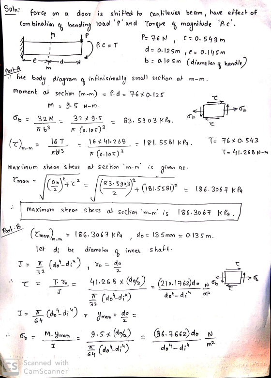
 Learning Goal: To calculate torsional deformation and shear stress due to an applied force in a door handle design. A locked door handle is composed of a solid circular shaft AB with a diameter fb = 105 mm and a flat plate BC with a force P = 76 N applied at point C as shown. Let c = 543 mm, d = 125 mm, and e = 145 mm. (Treat the handle as if it were a cantilever beam.)...
Learning Goal: To calculate torsional deformation and shear stress due to an applied force in a...
 Learning Goal: To calculate torsional deformation and shear stress due to an applied force in a door handle design. A locked door handle is composed of a solid circular shaft AB with a diameter of b = 101 mm and a flat plate BC with a force P = 77 N applied at point C as shown. Let c = 473 mm, d = 126 mm, and e = 148 mm (Treat the handle as if it were a cantilever...
Torsional Deformation of a Circular Shaft Learning Goal: To calculate torsional deformation and s...
 Torsional Deformation of a Circular Shaft Learning Goal: To calculate torsional deformation and shear stress due to an applied force in a door handle design. A locked door handle is composed of a solid orcular shaft AB with a diameter of b 101 mm and a flat plate BC with a ferce P-65 N applied at point C as shown Let c 523 mm,d 135 mm, and e 157 mm (Treat the hande as if it were a cantilever beam)...
Homework 4 porsional Deformation of a Circular Shaft Learning Goal locacao sinal de and shared to...
 Homework 4 porsional Deformation of a Circular Shaft Learning Goal locacao sinal de and shared to anaped for en a Aloed door handles composed of scrush Al Wadiameter ndere 100 mandate with a force P.14 Naleport as shown Leemed 12mmande 15m (hte handie s e werbe Part A Mano Shermocon. mon d by the Express the shear stress to the significatures and include appropriate unit View Available Type here to search A D 18 PM 1125/2019 14 ° 5 °6...
Learning Goal: To determine the maximum shear force that can be applied to two shafts of...
 Learning Goal: To determine the maximum shear force that can be applied to two shafts of varying cross sections: a solid square shaft and a hollow square shaft. The two square cross sections shown below (Figure 1) are each subjected to a vertical shear force, V. The side length of each cross section is s = 6.00 in and the side length of the hollowed- out portion of the second cross section is r = 2.25 in. The maximum allowable...
Learning Goal: To determine the state of stress in a solid rod using the principle of...
 Learning Goal: To determine the state of stress in a solid rod using the principle of superposition. A solid rod has a diameter of e = 55 mm and is subjected to the loading shown. Let a = 190 mm, b = 220 mm , c = 350 mm, d = 240 mm , and P = 4.0 kN. Take point A to be at the top of the circular cross-section. (Figure 1) Figure < 1 of 2 b В...
Learning Goal: To calculate the shear stress at the web/flange joint in a beam and use...
 Learning Goal: To calculate the shear stress at the web/flange joint in a beam and use that stress to calculate the required nail spacing to make a built- up beam. A built up beam can be constructed by fastening flat plates together. When an l-beam is subjected to a shear load, internal shear stress is developed at every cross section, with longitudinal shear stress balancing transverse shear stress. If the beam is built up using plates, the fasteners used must...
To determine the maximum shear force that can be applied to two shafts of varying cross sections: a solid square shaft and a hollow square shaft.
 Learning Goal: To determine the maximum shear force that can be applied to two shafts of varying cross sections: a solid square shaft and a hollow square shaft. The two square cross sections shown below (Figure 1) are each subjected to a vertical shear force, V. The side length of each cross section is s = 6.75 in and the side length of the hollowed-out portion of the second cross section is r = 4.00 in. The maximum allowable shear stress in...
Leaming Goal: To determine the shear stresses at specific locations in a beam due to an...
 Leaming Goal: To determine the shear stresses at specific locations in a beam due to an external loading. Beam ABC is subjected to the loading shown, where PB = 40.0 kN. The measurement corresponding to the half-length of the beam is a = 2.50 m. For the cross section shown, b = 50.0 mm, c= 125.0 mm, d = 125.0 mm, and e = 65.0 mm Point Dis located at the centroid of the cross section and point E is...
 Learning Goal: To calculate torsional deformation and shear stress due to an applied force in a door handle design. A locked door handle is composed of a solid circular shaft AB with a diameter fb = 105 mm and a flat plate BC with a force P = 76 N applied at point C as shown. Let c = 543 mm, d = 125 mm, and e = 145 mm. (Treat the handle as if it were a cantilever beam.)...
 Learning Goal: To calculate torsional deformation and shear stress due to an applied force in a door handle design. A locked door handle is composed of a solid circular shaft AB with a diameter of b = 101 mm and a flat plate BC with a force P = 77 N applied at point C as shown. Let c = 473 mm, d = 126 mm, and e = 148 mm (Treat the handle as if it were a cantilever...
 Torsional Deformation of a Circular Shaft Learning Goal: To calculate torsional deformation and shear stress due to an applied force in a door handle design. A locked door handle is composed of a solid orcular shaft AB with a diameter of b 101 mm and a flat plate BC with a ferce P-65 N applied at point C as shown Let c 523 mm,d 135 mm, and e 157 mm (Treat the hande as if it were a cantilever beam)...
 Homework 4 porsional Deformation of a Circular Shaft Learning Goal locacao sinal de and shared to anaped for en a Aloed door handles composed of scrush Al Wadiameter ndere 100 mandate with a force P.14 Naleport as shown Leemed 12mmande 15m (hte handie s e werbe Part A Mano Shermocon. mon d by the Express the shear stress to the significatures and include appropriate unit View Available Type here to search A D 18 PM 1125/2019 14 ° 5 °6...
 Learning Goal: To determine the maximum shear force that can be applied to two shafts of varying cross sections: a solid square shaft and a hollow square shaft. The two square cross sections shown below (Figure 1) are each subjected to a vertical shear force, V. The side length of each cross section is s = 6.00 in and the side length of the hollowed- out portion of the second cross section is r = 2.25 in. The maximum allowable...
 Learning Goal: To determine the state of stress in a solid rod using the principle of superposition. A solid rod has a diameter of e = 55 mm and is subjected to the loading shown. Let a = 190 mm, b = 220 mm , c = 350 mm, d = 240 mm , and P = 4.0 kN. Take point A to be at the top of the circular cross-section. (Figure 1) Figure < 1 of 2 b В...
 Learning Goal: To calculate the shear stress at the web/flange joint in a beam and use that stress to calculate the required nail spacing to make a built- up beam. A built up beam can be constructed by fastening flat plates together. When an l-beam is subjected to a shear load, internal shear stress is developed at every cross section, with longitudinal shear stress balancing transverse shear stress. If the beam is built up using plates, the fasteners used must...
 Leaming Goal: To determine the shear stresses at specific locations in a beam due to an external loading. Beam ABC is subjected to the loading shown, where PB = 40.0 kN. The measurement corresponding to the half-length of the beam is a = 2.50 m. For the cross section shown, b = 50.0 mm, c= 125.0 mm, d = 125.0 mm, and e = 65.0 mm Point Dis located at the centroid of the cross section and point E is...
Most questions answered within 3 hours.
-
Task 5.2 Numerical Analysis Using Nested Loops (13 pts)
Consider the following program:
void setup()
{...
asked 11 minutes ago -
If a lossless transformer has 1000 turns for a primary winding
and 100 turns for the...
asked 19 minutes ago -
Write the net ionic equation for the precipitation reaction that
occurs when aqueous solutions of potassium...
asked 28 minutes ago -
it
should be written in c++
Your program should take numbers from the user until the...
asked 34 minutes ago -
Buses are powered by chemical reactions. Define matter and the
four states of matter. What is...
asked 52 minutes ago -
Use conservation of energy to find the velocity of a free point
charge q1 at 22cm...
asked 59 minutes ago -
First, describe policies promoted by governments of the
political right to address economic globalization. Second, describe...
asked 1 hour ago -
M2-9 Completing T-Accounts LO2-4
Following are the transactions of Dennen, Inc., for the month of
January....
asked 1 hour ago -
Write a program using python that reads from values from a text
file and plots them...
asked 1 hour ago -
Look up the density of
the metal of the object used in parts A and B...
asked 1 hour ago -
Discuss strategic considerations that Amazon and NYC politicians
had. Analyze why the deal between Amazon and...
asked 1 hour ago -
A combustion reaction is describes as a carbon source reacting
with oxygen and producing carbon dioxide...
asked 1 hour ago