

Homework Answers
Add Answer to:
u Review Part B - Calculate the moment of inertia Learning Goal: To find the centroid...
Learning Goal: To calculate the shear stress at the web/flange joint in a beam and use...
 Learning Goal: To calculate the shear stress at the web/flange joint in a beam and use that stress to calculate the required nail spacing to make a built- up beam. A built up beam can be constructed by fastening flat plates together. When an l-beam is subjected to a shear load, internal shear stress is developed at every cross section, with longitudinal shear stress balancing transverse shear stress. If the beam is built up using plates, the fasteners used must...
The Flexure Formula 6 of 6 Learning Goal: To determine an I-beam's maximum bending moment, moment...
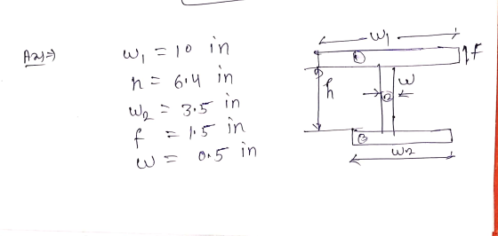
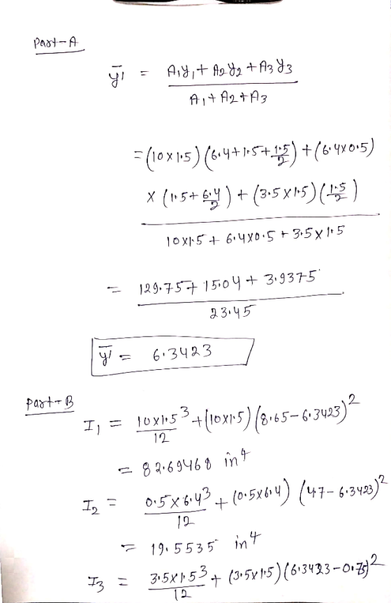
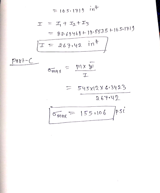
 The Flexure Formula 6 of 6 Learning Goal: To determine an I-beam's maximum bending moment, moment of inertia using the parallel-axis theorem, and the maximum stress at a given location using the flexure formula. As shown, I-beam ABC supports a sign that weighs S 27 lb. The I-beam is 24 in. long and is further supported by a rod that is attached 16 in. from the wall. Assume that all forces acting on the I-beam act along its centroid and...
Part A - Moment about the x axis at A Learning Goal: To determine the state...
 Part A - Moment about the x axis at A Learning Goal: To determine the state of stress in a solid rod using the principle of superposition. A solid rod has a diameter of e = 60 mm and is subjected to the loading shown. Let a = 200 mm, b = 220 mm c = 340 mm, d = 230 mm, and P = 4.0 kN. Take point A to be at the top of the circular cross-section. (Figure...
b) Calculate moment of inertia of cross section about the z' axis that passes the center...
 b) Calculate moment of inertia of cross section about the z' axis that passes the center of area 0 as shown in the figure. (find center of area y first) YE d-3 in Sin S.S in s in c) ( D ) The max shear stress in a solid round shaft subjected only to torsion occurs: a) on principal planes b) on planes containing the axis of the shaft c) on the surface of the shaft d) only on planes...
Review Learning Goal: To use the superposition principle to find the state of stress on a...
 Review Learning Goal: To use the superposition principle to find the state of stress on a beam under multiple loadings The beam shown below is subjected to a horizontal force P via the rope wound around the pulley. The state of stress at point A is to be determined. Part A - Support Reactions and Internal Loading Determine the support reactions Cy and Cz and the internal normal force, shear force, and moment on the cross-section containing point A. Express...
Learning Goal: To calculate the normal and shear stresses at a point on the cross section...
 Learning Goal: To calculate the normal and shear stresses at a point on the cross section of a column. The state of stress at a point is a description of the normal and shear stresses at that point. The normal stresses are generally due to both internal normal force and internal bending moment. The net result can be obtained using the principle of superposition as long as the deflections remain small and the response is elastic. Figure < 1 of...
Take that a (Figure 1) 50 mm Part A Determine the distance to the centroid of...
 Take that a (Figure 1) 50 mm Part A Determine the distance to the centroid of the beam's cross-sectional area Express your answer to three significant figures and include the appropriate units z= | Value | Units | Submit Request Answer Part B Find the moment of inertia about the y axis. Express your answer to three significant figures and include the appropriate units LA IValue Units Figure 1 of 1 Submit Request Answer < Return to Assignment Provide Feedback
Please show all steps and applicable diagrams a = 2.0m b = 4.0m c = 2.0m...
 Please show all steps and applicable diagrams
a = 2.0m
b = 4.0m
c = 2.0m
d = 6.0m
e = 3.0m
M = 48kN*m
w1 = 8kN/m
w2 = 6kN/m
W1 W2 M BE 5 •d ye Beam DBE has the cross-section shown in the figure to the right Calculate: c) the vertical position y, of the centroid of the girder cross-section, and d) the moment of inertia Ix' about the horizontal axis x'x' passing through the centroid of...
Please show all steps and applicable diagrams
a = 2.0m
b = 4.0m
c = 2.0m
d = 6.0m
e = 3.0m
M = 48kN*m
w1 = 8kN/m
w2 = 6kN/m
W1 W2 M BE 5 •d ye Beam DBE has the cross-section shown in the figure to the right Calculate: c) the vertical position y, of the centroid of the girder cross-section, and d) the moment of inertia Ix' about the horizontal axis x'x' passing through the centroid of...
For the beam shown in the given figure:
 For the beam shown in the given figure: (a) Express the internal shear (V) and moment (M) in the beam as a function of x. (b) Draw the shear force diagram (SFD) and bending moment diagram (BMD). (c) If the area moment of inertia (I) of the beam's cross section about the neutral axis is 301.3 (10-6)m4, determine the absolute maximum bending stress (σmax) in the beam.
Learning Goal: To be able to calculate the moment of inertia of composite areas An object's...
 Learning Goal: To be able to calculate the moment of inertia of composite areas An object's moment of inertia is calculated analytically via Integration, which involves dividing the object's aren into the elemental strips that are parallel to the axes and then performing the integration of the strip's moment of inertia correct The parallel-axis theorem is used in the calculation of the moment of inertia for composite areas. Here, the reference axis coincides with the rectangle's base and semicircle's diameter....
 Learning Goal: To calculate the shear stress at the web/flange joint in a beam and use that stress to calculate the required nail spacing to make a built- up beam. A built up beam can be constructed by fastening flat plates together. When an l-beam is subjected to a shear load, internal shear stress is developed at every cross section, with longitudinal shear stress balancing transverse shear stress. If the beam is built up using plates, the fasteners used must...
 The Flexure Formula 6 of 6 Learning Goal: To determine an I-beam's maximum bending moment, moment of inertia using the parallel-axis theorem, and the maximum stress at a given location using the flexure formula. As shown, I-beam ABC supports a sign that weighs S 27 lb. The I-beam is 24 in. long and is further supported by a rod that is attached 16 in. from the wall. Assume that all forces acting on the I-beam act along its centroid and...
 Part A - Moment about the x axis at A Learning Goal: To determine the state of stress in a solid rod using the principle of superposition. A solid rod has a diameter of e = 60 mm and is subjected to the loading shown. Let a = 200 mm, b = 220 mm c = 340 mm, d = 230 mm, and P = 4.0 kN. Take point A to be at the top of the circular cross-section. (Figure...
 b) Calculate moment of inertia of cross section about the z' axis that passes the center of area 0 as shown in the figure. (find center of area y first) YE d-3 in Sin S.S in s in c) ( D ) The max shear stress in a solid round shaft subjected only to torsion occurs: a) on principal planes b) on planes containing the axis of the shaft c) on the surface of the shaft d) only on planes...
 Review Learning Goal: To use the superposition principle to find the state of stress on a beam under multiple loadings The beam shown below is subjected to a horizontal force P via the rope wound around the pulley. The state of stress at point A is to be determined. Part A - Support Reactions and Internal Loading Determine the support reactions Cy and Cz and the internal normal force, shear force, and moment on the cross-section containing point A. Express...
 Learning Goal: To calculate the normal and shear stresses at a point on the cross section of a column. The state of stress at a point is a description of the normal and shear stresses at that point. The normal stresses are generally due to both internal normal force and internal bending moment. The net result can be obtained using the principle of superposition as long as the deflections remain small and the response is elastic. Figure < 1 of...
 Take that a (Figure 1) 50 mm Part A Determine the distance to the centroid of the beam's cross-sectional area Express your answer to three significant figures and include the appropriate units z= | Value | Units | Submit Request Answer Part B Find the moment of inertia about the y axis. Express your answer to three significant figures and include the appropriate units LA IValue Units Figure 1 of 1 Submit Request Answer < Return to Assignment Provide Feedback
 Please show all steps and applicable diagrams
a = 2.0m
b = 4.0m
c = 2.0m
d = 6.0m
e = 3.0m
M = 48kN*m
w1 = 8kN/m
w2 = 6kN/m
W1 W2 M BE 5 •d ye Beam DBE has the cross-section shown in the figure to the right Calculate: c) the vertical position y, of the centroid of the girder cross-section, and d) the moment of inertia Ix' about the horizontal axis x'x' passing through the centroid of...
Please show all steps and applicable diagrams
a = 2.0m
b = 4.0m
c = 2.0m
d = 6.0m
e = 3.0m
M = 48kN*m
w1 = 8kN/m
w2 = 6kN/m
W1 W2 M BE 5 •d ye Beam DBE has the cross-section shown in the figure to the right Calculate: c) the vertical position y, of the centroid of the girder cross-section, and d) the moment of inertia Ix' about the horizontal axis x'x' passing through the centroid of...
 Learning Goal: To be able to calculate the moment of inertia of composite areas An object's moment of inertia is calculated analytically via Integration, which involves dividing the object's aren into the elemental strips that are parallel to the axes and then performing the integration of the strip's moment of inertia correct The parallel-axis theorem is used in the calculation of the moment of inertia for composite areas. Here, the reference axis coincides with the rectangle's base and semicircle's diameter....
Most questions answered within 3 hours.
-
A sample survey at a supermarket showed that 204 of 300 shoppers
regularly use cents-off coupons....
asked 25 seconds ago -
What is the HDI (Hydrogen Deficiency Index) for acetic acid? How
many sets of non-equivalent protons...
asked 1 minute ago -
Disease Prevention and Health Promotion-Topic
What are the roles of both the state and federal government...
asked 5 minutes ago -
determine the following probabilites
a. for n= 3 and (pie)π = 0.16, what is P(X=0)?
b....
asked 8 minutes ago -
Why do men earn more money than women in America?
asked 18 minutes ago -
Sales of tablet computers at Ted Glickman's electronics store
in Washington, D.C., over the past 10...
asked 28 minutes ago -
Short essay question:
First, discuss the anatomical differences between Paleocene
pro-primates and Eocene eu-primates and explain...
asked 28 minutes ago -
Suppose we have a binomial experiment in which success is
defined to be a particular quality...
asked 50 minutes ago -
march the type of cellular control with the description: enzyme
induction and the enzyme repression. How...
asked 59 minutes ago -
Brief Exercise 5-09 (Part Level Submission)
The following information relates to Blue Spruce Corp. for the...
asked 59 minutes ago -
An unknown amount of a compound with a molecular mass of 284.04
g/mol is dissolved in...
asked 1 hour ago -
You are at rest at a stop sign. There is another stop sign that
is 100...
asked 1 hour ago