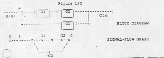
Ex. 192. Refer to the  system in Fig. 192
Determine the closed loop transfer function C/R = (As+B)/(s+D) where
G1=41, G2=1/(s+30), G3=17.  Determine A,B,D.  ans:3
Homework Answers


Add Answer to:
Ex. 192. Refer to the system in Fig. 192
Determine the closed loop transfer function C/R...
Find the closed-loop transfer function, T(s)-C(s)/R(s) for the following systems using block diagram reduction R(s)+ G1...
 Find the closed-loop transfer function, T(s)-C(s)/R(s) for the following systems using block diagram reduction R(s)+ G1 G2 G8 C(s) G2 G4 G7 G3 G1 G2 G3 G4. C(s) R(s)+ G5 G6 G7
3. There is a block diagram as shown in Fig. G1 G2 G3 Fig. 2 (a)...
 3. There is a block diagram as shown in Fig. G1 G2 G3 Fig. 2 (a) Convert the block diagram to a signal flow (b) Obtain its transfer function (G(s)-C(s)/R(s)) (c) As G -K.G3 G3 and its inputrt) is unit step, obtain the 50 condition of the P-controller(G1) for c(t) not to oscillate.
PROBLEMS B-2-1. Simplify the block diagram shown in Figure 2-29 and obtain the closed-loop transfer function...
 PROBLEMS B-2-1. Simplify the block diagram shown in Figure 2-29 and obtain the closed-loop transfer function C(s)/RS). B-2-2. Simplify the block diagram shown in Figure 2-30 and obtain the closed-loop transfer function C(s)/R(s). B-2-3. Simplify the block diagram shown in Figure 2-31 and obtain the closed-loop transfer function C(s)/R(S). G1 R(S) CS) Figure 2-29 Block diagram of a system. Figure 2-30 Block diagram of a system. Figure 2-31 Block diagram of a system.
1. Simplify the block diagram shown in the figure below. Then, obtain the closed-loop transfer function...
 1. Simplify the block diagram shown in the figure below. Then, obtain the closed-loop transfer function C(s) /R(s). Hi R(s) G1 Gix 1 C(s) H2 H3
2. Determine the closed-loop transfer function Y (using Signal Flow Graphs or Block U(s) Diagram Transformations)...
 2. Determine the closed-loop transfer function Y (using Signal Flow Graphs or Block U(s) Diagram Transformations) for the system shown in Figure 2 U(s) Y (s) 0 do
USE MASONS RULE (MASONS LOOP GAIN) METHOD TO REDUCE TO EQUIVALENT TRANSFER FUNCTION G1 C(s) G6...
 USE MASONS RULE (MASONS LOOP GAIN) METHOD TO REDUCE TO
EQUIVALENT TRANSFER FUNCTION
G1 C(s) G6 R(s) + G5 G2 + G3 G4 G7 FIGURE P5.9
USE MASONS RULE (MASONS LOOP GAIN) METHOD TO REDUCE TO
EQUIVALENT TRANSFER FUNCTION
G1 C(s) G6 R(s) + G5 G2 + G3 G4 G7 FIGURE P5.9
[HELP!] 1. Simplify the following block diagram. Obtain the transfer function from R to C for Fig. 1, and the transfer function from X(s) to Y(s) for Fig. 2. 2. Convert the block diagram of figures 1 and 2 to a signal flow graph.
 Simplify the following block diagram. Obtain the transfer function from R to C for Fig. 1,
and the transfer function from X(s) to Y(s) for Fig. 2.Convert the block diagram of figures 1 and 2 to a signal flow graph.Below are the diagrams:
Simplify the following block diagram. Obtain the transfer function from R to C for Fig. 1,
and the transfer function from X(s) to Y(s) for Fig. 2.Convert the block diagram of figures 1 and 2 to a signal flow graph.Below are the diagrams:
Determine: 1. The transfer function C(s)/R(s). Also find the closed-loop poles of the system. 2. The...
 Determine: 1. The transfer function C(s)/R(s). Also find the
closed-loop poles of the system. 2. The values of the undamped
natural frequency ωN and damping ratio ξ of the closed-loop poles.
3. The expressions of the rise time, the peak time, the maximum
overshoot, and the 2% settling time due to a unit-step reference
signal.
For the open-loop process with negative feedback R(S) Gp(S) C(s) H(s) 103 Go(s) = 1 , Gp(s)- s(s + 4) Determine: 1. The transfer function...
Determine: 1. The transfer function C(s)/R(s). Also find the
closed-loop poles of the system. 2. The values of the undamped
natural frequency ωN and damping ratio ξ of the closed-loop poles.
3. The expressions of the rise time, the peak time, the maximum
overshoot, and the 2% settling time due to a unit-step reference
signal.
For the open-loop process with negative feedback R(S) Gp(S) C(s) H(s) 103 Go(s) = 1 , Gp(s)- s(s + 4) Determine: 1. The transfer function...
s G1 = G2 = S-8 G2 s2+1 G3= G4 = R(s) C(s) S G1 G3...
 s G1 = G2 = S-8 G2 s2+1 G3= G4 = R(s) C(s) S G1 G3 G4 H1 H2 si 28+3 H1 H2 a) Find the characteristic equation by subtracting the transfer function (C (s) / R (s)) of the system, whose block diagram is given above. b) Determine the stability of the given system with Routh-Hurwitz stability analysis method.
Ex. 260. Refer to Fig. 220 with D=0, and R=1/s. Replace 1/(s+1) with A/(s+1) where the...
 Ex. 260. Refer to Fig. 220 with D=0, and R=1/s.
Replace 1/(s+1) with A/(s+1) where the nominal value of A is 1 but A can
increase 10% due to uncontrollable conditions.
a) Determine the open-loop (H=0) percentage change in steady-state output (Css)
when A increases 10%. b) Determine the closed-loop (H=1) percentage change in
output (Css) when A increases 10% and k=66. Hint: Three significant
figures in the final results may require more significant figures
in the intermediate results. ans:2...
Ex. 260. Refer to Fig. 220 with D=0, and R=1/s.
Replace 1/(s+1) with A/(s+1) where the nominal value of A is 1 but A can
increase 10% due to uncontrollable conditions.
a) Determine the open-loop (H=0) percentage change in steady-state output (Css)
when A increases 10%. b) Determine the closed-loop (H=1) percentage change in
output (Css) when A increases 10% and k=66. Hint: Three significant
figures in the final results may require more significant figures
in the intermediate results. ans:2...
 Find the closed-loop transfer function, T(s)-C(s)/R(s) for the following systems using block diagram reduction R(s)+ G1 G2 G8 C(s) G2 G4 G7 G3 G1 G2 G3 G4. C(s) R(s)+ G5 G6 G7
 3. There is a block diagram as shown in Fig. G1 G2 G3 Fig. 2 (a) Convert the block diagram to a signal flow (b) Obtain its transfer function (G(s)-C(s)/R(s)) (c) As G -K.G3 G3 and its inputrt) is unit step, obtain the 50 condition of the P-controller(G1) for c(t) not to oscillate.
 PROBLEMS B-2-1. Simplify the block diagram shown in Figure 2-29 and obtain the closed-loop transfer function C(s)/RS). B-2-2. Simplify the block diagram shown in Figure 2-30 and obtain the closed-loop transfer function C(s)/R(s). B-2-3. Simplify the block diagram shown in Figure 2-31 and obtain the closed-loop transfer function C(s)/R(S). G1 R(S) CS) Figure 2-29 Block diagram of a system. Figure 2-30 Block diagram of a system. Figure 2-31 Block diagram of a system.
 1. Simplify the block diagram shown in the figure below. Then, obtain the closed-loop transfer function C(s) /R(s). Hi R(s) G1 Gix 1 C(s) H2 H3
 2. Determine the closed-loop transfer function Y (using Signal Flow Graphs or Block U(s) Diagram Transformations) for the system shown in Figure 2 U(s) Y (s) 0 do
 USE MASONS RULE (MASONS LOOP GAIN) METHOD TO REDUCE TO
EQUIVALENT TRANSFER FUNCTION
G1 C(s) G6 R(s) + G5 G2 + G3 G4 G7 FIGURE P5.9
USE MASONS RULE (MASONS LOOP GAIN) METHOD TO REDUCE TO
EQUIVALENT TRANSFER FUNCTION
G1 C(s) G6 R(s) + G5 G2 + G3 G4 G7 FIGURE P5.9
 Determine: 1. The transfer function C(s)/R(s). Also find the
closed-loop poles of the system. 2. The values of the undamped
natural frequency ωN and damping ratio ξ of the closed-loop poles.
3. The expressions of the rise time, the peak time, the maximum
overshoot, and the 2% settling time due to a unit-step reference
signal.
For the open-loop process with negative feedback R(S) Gp(S) C(s) H(s) 103 Go(s) = 1 , Gp(s)- s(s + 4) Determine: 1. The transfer function...
Determine: 1. The transfer function C(s)/R(s). Also find the
closed-loop poles of the system. 2. The values of the undamped
natural frequency ωN and damping ratio ξ of the closed-loop poles.
3. The expressions of the rise time, the peak time, the maximum
overshoot, and the 2% settling time due to a unit-step reference
signal.
For the open-loop process with negative feedback R(S) Gp(S) C(s) H(s) 103 Go(s) = 1 , Gp(s)- s(s + 4) Determine: 1. The transfer function...
 s G1 = G2 = S-8 G2 s2+1 G3= G4 = R(s) C(s) S G1 G3 G4 H1 H2 si 28+3 H1 H2 a) Find the characteristic equation by subtracting the transfer function (C (s) / R (s)) of the system, whose block diagram is given above. b) Determine the stability of the given system with Routh-Hurwitz stability analysis method.
Most questions answered within 3 hours.
-
You're examining some of the tiny printing on one of the newer
twenty-dollar bills. A 1.5...
asked 31 seconds from now -
Discuss several common sources of secondary data coming from
government sources.
asked 2 minutes ago -
This is a basic java program where you convert units using only
loops, control statements and...
asked 2 minutes ago -
A sample survey at a supermarket showed that 204 of 300 shoppers
regularly use cents-off coupons....
asked 47 minutes ago -
1. Find the area under the standard normal curve that lies
outside the interval between z=...
asked 19 minutes ago -
In ________ mode, the interpreter reads the contents of a file
that contains Python statements and...
asked 34 minutes ago -
1.
The second-order rate constant for self-reaction of hydroxyl
radicals
2 OH → H2O + O...
asked 24 minutes ago -
What is the most important factor leading to improved resource
efficiency over the long run?
asked 21 minutes ago -
Defend the effectiveness of teamwork in an organization.
(Use no more than 30 words)
asked 22 minutes ago -
Promotional strategies can assist in moving a product through
the channel of distribution. (a) Briefly explain...
asked 23 minutes ago -
Discuss why new and improved security measures are not enough to
stop online crime, What is...
asked 28 minutes ago -
A person whose weight is 516 N is being pulled up vertically by
a rope from...
asked 41 minutes ago