
Homework Answers
Let w=frequency in rad / sec of reference phasor
TIME DOMAIN to PHASOR - DOMAIN
Resistance (R) ----------------------> R
Inductive Impedance (L) ----------------------> jwL
Capacitive Impedance (C) --------------------> 1/(jwC)
Basics
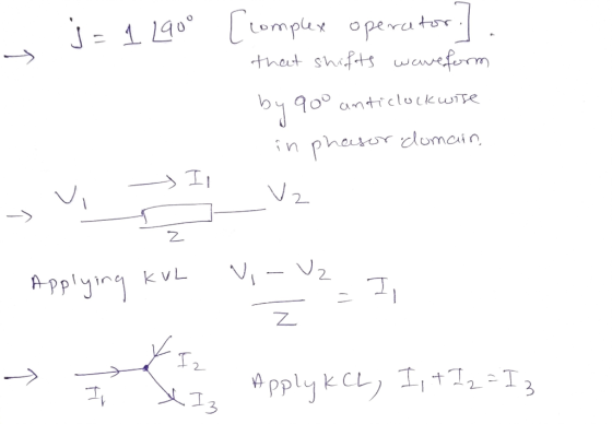
Kirchhoff's Current Law: For a lumped network, algebraic sum of currents entering (or leaving) a node is equal to zero for every instant of time.
Kirchhoff's Voltage Law: For a lumped network, algebraic sum of voltages in any close path is equal to zero for every instant of time.
Lumped network is a network in which the network components i.e., R,L and C can be separated.
Now, Let us solve the problem.


![=> (V-V2) ( 8- 5j) +jiov, zo >>|(875j]v+ C5j-8) Va=0 - a Apply Kul in mode (N2), following squette y KuL in wing equation noc](http://img.homeworklib.com/questions/935d84a0-b082-11ea-954c-9f335d445d81.png?x-oss-process=image/resize,w_560)

%MATLAB CODE
clear all
clc
Xc=4/i;
A=[8+5*i 5*i-8;80+39*i -(160+103*i)]; %Create A matrix
B=[0;-7.9969e+02 - 4.2511e+02i];
X= inv(A)*B; % Multiplying A inverse with B to get solution
V1=X(1);
V2=X(2);
Ic=V1/Xc;
display('Amplitude of Ic(t)')
Amp=abs(Ic)
display('Phase angle of Ic(t) in degrees')
phi=angle(Ic)*180/pi
syms amp_ic ph_ic f_ic
amp_ic = Amp
ph_ic = phi
f_ic =400


Add Answer to:
HW5 Problem 1 Creating Symbolic Expressions My Solutions > Problemi In the circuit below, the voltage...
1) In the circuit below the currents are named A, and lc The current direction is determined by the source (out of positive terminal) in the middle and right branches and is clockwise in the left bra...
 1) In the circuit below the currents are named A, and lc The current direction is determined by the source (out of positive terminal) in the middle and right branches and is clockwise in the left branch · IA flows through R2 and R1 Is flows through R4 and Vb cflows through R3, Vc AB R2 R3 R4 R1 Vb a) Draw the circuit and show the 3 currents described above, including arrows showing the current direction. Show the voltage...
Circuit Analysis in the s-Domain 15.3. The initial voltage across the capacitor in the circuit shown in Figure P15.3 is v(0) 1 V, and the initial current through the inductor is i(0)0 mA Find th...
 Circuit Analysis in the s-Domain 15.3. The initial voltage across the capacitor in the circuit shown in Figure P15.3 is v(0) 1 V, and the initial current through the inductor is i(0)0 mA Find the voltage vo (t) across the capacitor for t 2 0 Figure P15.3 50 mH 1 kS2 V. Volt) T 0.1 μF The circuit in the s-domain is shown below. R2 Va 1k 0.05s 1/(sC)-1e7/s Vo R1 2k V (0-ys 5/s 1/s 1 format long; 2...
Name: Section: Jan. 31, 2018 1. Consider the circuit shown in figure 1 (a) Write the...
 Name: Section: Jan. 31, 2018 1. Consider the circuit shown in figure 1 (a) Write the mesh-current equations for the circuit. DO NOT SOLVE. (b) Write the node.voltage equations for the cireuit. DO NOT SOLVE 2. Consider the circuit shown in figure 2. The sinusoidal source is v,(04 sin (100t+90) volts (a) Transform the circuit to the frequency domain. (b) Use phasors with the mesh-current method to find the steady state expression for i(t). (c) Find the average power absorbed...
1. Why can the DSO only measure node voltages when the Function Generator is the power supply in ...
 1. Why can the DSO only measure node voltages when the Function Generator is the power supply in a circuit (unless it is using a current probe)? 2. Consider Figure 1. According to the calculations in the lab handout, if Z-1kΩ +/6914, then the phase difference (фи-фі) between u(t) and i (t) is 34.6". a. If this v(t) and i(t) were displayed on a DSO (v(t) being a node voltage and using a current probe for i(t) as shown in...
Lab Procedure: Part 1: Source Free RC Circuit V(t) ilts C3 (R3 21ko 1uF IC=10V a)...
 Lab Procedure: Part 1: Source Free RC Circuit V(t) ilts C3 (R3 21ko 1uF IC=10V a) For the circuit shown above, provide the equation and calculate the following: 1. The source free equation for V(t) for V(O)= 10 volts 2. The equation for it) 3. V(t) and i(t) for t = t (one time constant) b) Now, enter the circuit using Multisim Schematic Capture. c) Simulate using Transient mode with a graphical output and verify graphical results with your calculations....
 1) In the circuit below the currents are named A, and lc The current direction is determined by the source (out of positive terminal) in the middle and right branches and is clockwise in the left branch · IA flows through R2 and R1 Is flows through R4 and Vb cflows through R3, Vc AB R2 R3 R4 R1 Vb a) Draw the circuit and show the 3 currents described above, including arrows showing the current direction. Show the voltage...
 Circuit Analysis in the s-Domain 15.3. The initial voltage across the capacitor in the circuit shown in Figure P15.3 is v(0) 1 V, and the initial current through the inductor is i(0)0 mA Find the voltage vo (t) across the capacitor for t 2 0 Figure P15.3 50 mH 1 kS2 V. Volt) T 0.1 μF The circuit in the s-domain is shown below. R2 Va 1k 0.05s 1/(sC)-1e7/s Vo R1 2k V (0-ys 5/s 1/s 1 format long; 2...
 Name: Section: Jan. 31, 2018 1. Consider the circuit shown in figure 1 (a) Write the mesh-current equations for the circuit. DO NOT SOLVE. (b) Write the node.voltage equations for the cireuit. DO NOT SOLVE 2. Consider the circuit shown in figure 2. The sinusoidal source is v,(04 sin (100t+90) volts (a) Transform the circuit to the frequency domain. (b) Use phasors with the mesh-current method to find the steady state expression for i(t). (c) Find the average power absorbed...
 1. Why can the DSO only measure node voltages when the Function Generator is the power supply in a circuit (unless it is using a current probe)? 2. Consider Figure 1. According to the calculations in the lab handout, if Z-1kΩ +/6914, then the phase difference (фи-фі) between u(t) and i (t) is 34.6". a. If this v(t) and i(t) were displayed on a DSO (v(t) being a node voltage and using a current probe for i(t) as shown in...
 Lab Procedure: Part 1: Source Free RC Circuit V(t) ilts C3 (R3 21ko 1uF IC=10V a) For the circuit shown above, provide the equation and calculate the following: 1. The source free equation for V(t) for V(O)= 10 volts 2. The equation for it) 3. V(t) and i(t) for t = t (one time constant) b) Now, enter the circuit using Multisim Schematic Capture. c) Simulate using Transient mode with a graphical output and verify graphical results with your calculations....
Most questions answered within 3 hours.
-
The blues made its way into many kinds of music. Eric Clapton,
The Beatles, and Elvis...
asked 52 minutes ago -
If you’re standing at the bottom of a hill and asked to evaluate
it while being...
asked 1 hour ago -
1. Which region has taken the lead in the world of
e-waste handling?
a) European Union...
asked 1 hour ago -
A 8.15- g bullet from a 9-mm pistol has a velocity of 366.0 m/s.
It strikes...
asked 3 hours ago -
The outstanding bonds of Alpha Extracts have a yield to maturity
of 7.4 percent and a...
asked 3 hours ago -
The Problem: The Case of the Harmonizing Vacations
Your CEO is exploring partnering with a European...
asked 4 hours ago -
A chemical equation is balanced by adding coefficients in front
of some formulas so that the...
asked 4 hours ago -
From the literature (reference your sources): What are the
lattice parameters of calcite and aragonite? Why...
asked 5 hours ago -
Your system is rejecting the question am asking which is
preceded by a case study. It...
asked 5 hours ago -
3. On January 2, 2000, Larry creates a trust with himself as
trustee. Larry as trustee...
asked 5 hours ago -
A member of the volleyball team spikes the ball. During this
process, she changes the velocity...
asked 5 hours ago -
Are adult gamers less likely to use a gaming console (Xbox,
PlayStation, Wii, etc...) than teen...
asked 6 hours ago