finite element
Homework Answers
Request Answer!
We need at least 9 more requests to produce the answer.
1 / 10 have requested this problem solution
The more requests, the faster the answer.
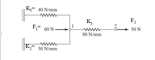
|Determine the displacements of nodes of the spring system shown below K=40 N/mm WW Кз 1...
 |Determine the displacements of nodes of the spring system shown below K=40 N/mm WW Кз 1 Fi= 60 N 50 N WWw 80 N/mm Ww K2= 50 N/mm
|Determine the displacements of nodes of the spring system shown below K=40 N/mm WW Кз 1 Fi= 60 N 50 N WWw 80 N/mm Ww K2= 50 N/mm
|Determine the displacements of nodes of the spring system shown below K=40 N/mm WW Кз 1 Fi= 60 N 50 N WWw 80 N/mm Ww K2= 50 N/mm
For the beam shown in below, determine the displacements and rotations at the nodes, the forces in each element, and reactions. Also, draw the shear force and bending moment diagrams 10 kN 2 E210 GPa...
 For the beam shown in below, determine the displacements and rotations at the nodes, the forces in each element, and reactions. Also, draw the shear force and bending moment diagrams 10 kN 2 E210 GPa .20 kN m
For the beam shown in below, determine the displacements and rotations at the nodes, the forces in each element, and reactions. Also, draw the shear force and bending moment diagrams 10 kN 2 E210 GPa .20 kN m
For the beam shown in below, determine the displacements and rotations at the nodes, the forces in each element, and reactions. Also, draw the shear force and bending moment diagrams 10 kN 2 E210 GPa .20 kN m
Determine the nodal displacements and reaction forces using the finite element direct method for the 1-D bar elements connected as shown below.
 Determine the nodal displacements and reaction forces using the finite element direct method for the 1-D bar elements connected as shown below. Do not rename the nodes or elements when solving. Assume that the bars can only undergo translation in x (1 DOF at each node). Nodes 1 and 3 are fixed Element 1 has Young's Modulus of 300 Pa, length of 1 m and cross-sectional area of 1 m2. Element 2 has Young's Modulus of 200 Pa, length of 2...
Problem 3. (3 points). Determine the nodal displacements and reaction forces using the finite element direct...
 Problem 3. (3 points). Determine the nodal displacements and reaction forces using the finite element direct method for the 1-D bar elements connected as shown below. Do not rename the nodes or elements when solving. Assume that the bars can only undergo translation in x (1 DOF at each node). Nodes 1 and 3 are fixed. Element 1 has Young's Modulus of 300 Pa, length of 1 m and cross-sectional area of m. Element 2 has Young's Modulus of 200...
by finite elemnt method 4. (25 points) Using symmetry on the frame shown below, solve for...
 by finite elemnt method
4. (25 points) Using symmetry on the frame shown below, solve for the unknown displacements and rotations. When setting up the stiffness matrix you may neglect terms that would be used to find the reactions. Use a consistent unit system from the table below. Note, the connections at nodes 2 and 4 are pins that do not allow X and Y displacements but do allow rotations. 60 KN 2 100 KN m 3 3 100 kNm...
by finite elemnt method
4. (25 points) Using symmetry on the frame shown below, solve for the unknown displacements and rotations. When setting up the stiffness matrix you may neglect terms that would be used to find the reactions. Use a consistent unit system from the table below. Note, the connections at nodes 2 and 4 are pins that do not allow X and Y displacements but do allow rotations. 60 KN 2 100 KN m 3 3 100 kNm...
Task of finite element
 A psysical structure is shown belowA. Purpose a fem axial model to represent the structure.Explain the element and the corresponding nodes using a table?B. State the constrains found in the structure
Three rigid bodies (Nodes 2, 3, and 4) are connected by five springs as shown below....
 Three rigid bodies (Nodes 2, 3, and 4) are connected by five
springs as shown below. Assume that the
bodies can only undergo translation in the horizontal direction.
Horizontal force P2=1000 N and
P4=1500 N is applied to Elements 2 and 4, respectively. The spring
constants in (N/mm) are given as:
k1=400, k2=500, k3=600, k4=100, and k5=300. Nodes 1 and 5 are
fixed. Determine the nodal
displacements and reaction forces at the walls.
Problem 1. (3 points) Three rigid bodies...
Three rigid bodies (Nodes 2, 3, and 4) are connected by five
springs as shown below. Assume that the
bodies can only undergo translation in the horizontal direction.
Horizontal force P2=1000 N and
P4=1500 N is applied to Elements 2 and 4, respectively. The spring
constants in (N/mm) are given as:
k1=400, k2=500, k3=600, k4=100, and k5=300. Nodes 1 and 5 are
fixed. Determine the nodal
displacements and reaction forces at the walls.
Problem 1. (3 points) Three rigid bodies...
Problem 4. (3 points). Determine the nodal displacements and reaction forces using the finite ele...
 Problem 4. (3 points). Determine the nodal displacements and reaction forces using the finite element direct method for the 1-D bar elements connected as shown below. Do not rename the nodes or elements when solving. Assume that bars can only undergo translation in x (1 DOF at each node). Nodes 1 and 4 are fixed Elements 1, 2 and 3 have Young's Modulus of Ei-300 Pa, E2-200 Pa, Es-200 Pa. All elements have o ae of 20 N 20 N...
For the spring assemblage shown in Figure 2-13, obtain (a) the global stiffness matrix, (b) the displacements of nodes 2-4, (c) the global nodal forces, and (d) the local element forces.
For the spring assemblage shown in Figure 2-13, obtain (a) the global stiffness matrix, (b) the displacements of nodes 2-4, (c) the global nodal forces, and (d) the local element forces. Node l is fixed while node 5 is given a fixed, known displacement δ= 20.0 mm. The spring constants are all equal to k = 200 kN/m.
For the truss shown in the below figure, determine the stifness matrix for each truss element,...
 For the truss shown in the below figure, determine the stifness
matrix for each truss element, the stiffness matrix for entire
truss, the displacements at nodes 1 through 4, and the force in
elements 1 through 5. Also, determine the force in each element.
Let A = 3 in2, E = 30 x 106
psi for all elements.
8 kips 8 kips 10 ft. 3 4 2 トー-10ft.-*-10 ft.
For the truss shown in the below figure, determine the stifness
matrix for each truss element, the stiffness matrix for entire
truss, the displacements at nodes 1 through 4, and the force in
elements 1 through 5. Also, determine the force in each element.
Let A = 3 in2, E = 30 x 106
psi for all elements.
8 kips 8 kips 10 ft. 3 4 2 トー-10ft.-*-10 ft.
 |Determine the displacements of nodes of the spring system shown below K=40 N/mm WW Кз 1 Fi= 60 N 50 N WWw 80 N/mm Ww K2= 50 N/mm
|Determine the displacements of nodes of the spring system shown below K=40 N/mm WW Кз 1 Fi= 60 N 50 N WWw 80 N/mm Ww K2= 50 N/mm
|Determine the displacements of nodes of the spring system shown below K=40 N/mm WW Кз 1 Fi= 60 N 50 N WWw 80 N/mm Ww K2= 50 N/mm
 For the beam shown in below, determine the displacements and rotations at the nodes, the forces in each element, and reactions. Also, draw the shear force and bending moment diagrams 10 kN 2 E210 GPa .20 kN m
For the beam shown in below, determine the displacements and rotations at the nodes, the forces in each element, and reactions. Also, draw the shear force and bending moment diagrams 10 kN 2 E210 GPa .20 kN m
For the beam shown in below, determine the displacements and rotations at the nodes, the forces in each element, and reactions. Also, draw the shear force and bending moment diagrams 10 kN 2 E210 GPa .20 kN m
 Determine the nodal displacements and reaction forces using the finite element direct method for the 1-D bar elements connected as shown below. Do not rename the nodes or elements when solving. Assume that the bars can only undergo translation in x (1 DOF at each node). Nodes 1 and 3 are fixed Element 1 has Young's Modulus of 300 Pa, length of 1 m and cross-sectional area of 1 m2. Element 2 has Young's Modulus of 200 Pa, length of 2...
 Problem 3. (3 points). Determine the nodal displacements and reaction forces using the finite element direct method for the 1-D bar elements connected as shown below. Do not rename the nodes or elements when solving. Assume that the bars can only undergo translation in x (1 DOF at each node). Nodes 1 and 3 are fixed. Element 1 has Young's Modulus of 300 Pa, length of 1 m and cross-sectional area of m. Element 2 has Young's Modulus of 200...
 by finite elemnt method
4. (25 points) Using symmetry on the frame shown below, solve for the unknown displacements and rotations. When setting up the stiffness matrix you may neglect terms that would be used to find the reactions. Use a consistent unit system from the table below. Note, the connections at nodes 2 and 4 are pins that do not allow X and Y displacements but do allow rotations. 60 KN 2 100 KN m 3 3 100 kNm...
by finite elemnt method
4. (25 points) Using symmetry on the frame shown below, solve for the unknown displacements and rotations. When setting up the stiffness matrix you may neglect terms that would be used to find the reactions. Use a consistent unit system from the table below. Note, the connections at nodes 2 and 4 are pins that do not allow X and Y displacements but do allow rotations. 60 KN 2 100 KN m 3 3 100 kNm...
 Three rigid bodies (Nodes 2, 3, and 4) are connected by five
springs as shown below. Assume that the
bodies can only undergo translation in the horizontal direction.
Horizontal force P2=1000 N and
P4=1500 N is applied to Elements 2 and 4, respectively. The spring
constants in (N/mm) are given as:
k1=400, k2=500, k3=600, k4=100, and k5=300. Nodes 1 and 5 are
fixed. Determine the nodal
displacements and reaction forces at the walls.
Problem 1. (3 points) Three rigid bodies...
Three rigid bodies (Nodes 2, 3, and 4) are connected by five
springs as shown below. Assume that the
bodies can only undergo translation in the horizontal direction.
Horizontal force P2=1000 N and
P4=1500 N is applied to Elements 2 and 4, respectively. The spring
constants in (N/mm) are given as:
k1=400, k2=500, k3=600, k4=100, and k5=300. Nodes 1 and 5 are
fixed. Determine the nodal
displacements and reaction forces at the walls.
Problem 1. (3 points) Three rigid bodies...
 Problem 4. (3 points). Determine the nodal displacements and reaction forces using the finite element direct method for the 1-D bar elements connected as shown below. Do not rename the nodes or elements when solving. Assume that bars can only undergo translation in x (1 DOF at each node). Nodes 1 and 4 are fixed Elements 1, 2 and 3 have Young's Modulus of Ei-300 Pa, E2-200 Pa, Es-200 Pa. All elements have o ae of 20 N 20 N...
 For the truss shown in the below figure, determine the stifness
matrix for each truss element, the stiffness matrix for entire
truss, the displacements at nodes 1 through 4, and the force in
elements 1 through 5. Also, determine the force in each element.
Let A = 3 in2, E = 30 x 106
psi for all elements.
8 kips 8 kips 10 ft. 3 4 2 トー-10ft.-*-10 ft.
For the truss shown in the below figure, determine the stifness
matrix for each truss element, the stiffness matrix for entire
truss, the displacements at nodes 1 through 4, and the force in
elements 1 through 5. Also, determine the force in each element.
Let A = 3 in2, E = 30 x 106
psi for all elements.
8 kips 8 kips 10 ft. 3 4 2 トー-10ft.-*-10 ft.
Most questions answered within 3 hours.
-
Please explain steps:
An 80 kg swimmer steps off a platform 10 m above the water...
asked 9 minutes ago -
A lottery exists where balls numbered 1 to 17 are placed in an
urn. To win,...
asked 12 minutes ago -
26) Briefly describe, using words or simple diagrams, the
chemiosmotic theory for coupling oxidation to phosphorylation...
asked 2 hours ago -
Suppose that XX is a random variable with mean 16 and standard
deviation 5 . Also...
asked 2 hours ago -
Calculate the number density of argon gas at a temperature of
24C and a pressure of...
asked 6 hours ago -
Alternative
Classification
How to Estimate
Probabilities from Data? ( For continuous Attributes)
And How to generate...
asked 6 hours ago -
An explosion breaks a 20.0-kg object into three parts. The
object is initially moving at a...
asked 7 hours ago -
Calculate the approximate number of residues of Rubisco, which
is involved in carbon fixation in plants,...
asked 8 hours ago -
Other decisions about scientific claims can have a much broader
impact.ENERGYarrow-10x10.png, environment, health, security - all...
asked 8 hours ago -
I need to write a research paper and work cited about this
topic: The United States...
asked 9 hours ago -
Hello! I was wondering if I could have some help?
If the vapor pressure of carvone...
asked 9 hours ago -
An economist wants to estimate the mean per capita income (in
thousands of dollars) for a...
asked 10 hours ago