
Homework Answers


Add Answer to:
A 5-m-long simply supported timber beam carries two concentrated loads as shown dimensions of the beam...
7.26 Torking stress in either tension or compression is AMS. 92.8 mm x 185.6 mm o MPa. am 3 m long is simply supported at each end and carries a uniformly distributed load of 10 kN/m. The beam...
 7.26
Torking stress in either tension or compression is AMS. 92.8 mm x 185.6 mm o MPa. am 3 m long is simply supported at each end and carries a uniformly distributed load of 10 kN/m. The beam at rectangular cross section, 75 mm x 150 mm. Determine the magnitude and location of the peak bending ress. Also, find the magnitude of the bending stress at a point 25 mm below the upper surface at the section midway betwcen supports....
7.26
Torking stress in either tension or compression is AMS. 92.8 mm x 185.6 mm o MPa. am 3 m long is simply supported at each end and carries a uniformly distributed load of 10 kN/m. The beam at rectangular cross section, 75 mm x 150 mm. Determine the magnitude and location of the peak bending ress. Also, find the magnitude of the bending stress at a point 25 mm below the upper surface at the section midway betwcen supports....
A simply supported wood beam of rectangular cross section and span length 2 m carries a...
 A simply supported wood beam of rectangular cross section and span length 2 m carries a uniformly distributed load of intensity 9 = 1 kN/m as shown. Calculate the maximum bending stress and the maximum shear stress in the beam.
P9.007 (GO Tutorial) A 6.8 m long simply supported wood beam carries a uniformly distributed load...
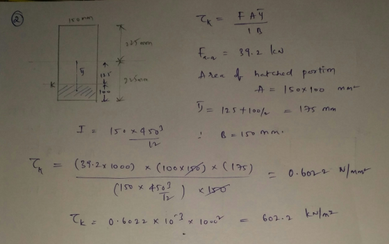
 P9.007 (GO Tutorial) A 6.8 m long simply supported wood beam carries a uniformly distributed load of 10.6 kN/m, as shown in Figure A. The cross-sectional dimensions of the beam as shown in Figure B are b = 180 mm, d-460 mm, ун-92 mm, and VK-1 44 mm. Section a-a is located at x-1.3 m from B (a) At section a-a, determine the magnitude of the shear stress in the beam at point H. (b) At section a-a, determine the...
A5.2 m long simply supported wood beam carries a uniformly distributed load of 12.9 kN/m, as...
 A5.2 m long simply supported wood beam carries a uniformly distributed load of 12.9 kN/m, as shown in Figure A. The cross-sectional dimensions of the beam as shown in Figure Bare b = 195 mm, d = 485 mm. yy = 81 mm, and yx = 167 mm. Section 3-a is located at x = 1.4 m from B. (a) At section a-a, determine the magnitude of the shear stress in the beam at point H. (b) At section a-3,...
A concentrated force P is applied in the middle of a simply supported beam with the T-shaped cross section shown. The m...
 A concentrated force P is applied in the middle of a simply supported beam with the T-shaped cross section shown. The maximum value of the load P so that the normal stress in the beam does not exceed 25 MPa is most closely: 150 mm P 30 mm 4m 4m 120 mm A' B A 40 mm A. 3.1 kN B. 5.8 kN Oc. 2.5 kN D. 4.3 kN
A concentrated force P is applied in the middle of a...
A concentrated force P is applied in the middle of a simply supported beam with the T-shaped cross section shown. The maximum value of the load P so that the normal stress in the beam does not exceed 25 MPa is most closely: 150 mm P 30 mm 4m 4m 120 mm A' B A 40 mm A. 3.1 kN B. 5.8 kN Oc. 2.5 kN D. 4.3 kN
A concentrated force P is applied in the middle of a...
Q2 A simply supported beam of length L = 10 m carries a uniformly distributed load...
 Q2 A simply supported beam of length L = 10 m carries a uniformly distributed load w of 10 kN/m, as shown in Figure Q2 (a). The beam is made from a symmetrical I-section and consists of three equal rectangular members of 100 mm x 10 mm (see Figure Q2 (b)). Self- weight of the beam is neglected. 100 mm w = 10 kN/m A- - A 100 mm 77777 L/3 L/3 L/3 — Figure Q2 (a) Figure Q2 (b)...
The W33 x221 steel simply supported beam is loaded with concentrated loads and uniform load as...
 The W33 x221 steel simply supported beam is loaded with
concentrated loads and uniform
load as shown with the load P= 150kip and w = 10kip/ft. For
this beam do the following;
a) Draw the shear and bending moment diagram
b) Calculate the maximum compressive and tensile stress
c) Calculate the maximum shear stress
P Р 3 ft 3 ft w 10 ft
The W33 x221 steel simply supported beam is loaded with
concentrated loads and uniform
load as shown with the load P= 150kip and w = 10kip/ft. For
this beam do the following;
a) Draw the shear and bending moment diagram
b) Calculate the maximum compressive and tensile stress
c) Calculate the maximum shear stress
P Р 3 ft 3 ft w 10 ft
Q1 A simply supported beam of length L = 10 m carries a uniformly distributed load...
 Q1 A simply supported beam of length L = 10 m carries a uniformly distributed load w = of 10 kN/m, as shown in Figure Q1 (a). The beam is made from a I-section and the thickness for all the three rectangular members is of 10 mm. All other dimensions are illustrated in Figure Q1 (b). Self-weight of the beam is neglected. 300 mm w = 10 kN/m 300 mm L/4 L/2 L/4 300 mm Figure Q1 (a) Figure Q1...
QI A simply supported beam of length L = 10 m carries a uniformly distributed load...
 QI A simply supported beam of length L = 10 m carries a uniformly distributed load w of 10 kN/m, as shown in Figure QI (a). The beam is made from a symmetrical I-section and consists of three equal rectangular members of 100 mm x 10 mm (see Figure QI (b)). Self- weight of the beam is neglected. 100 mm w = 10 kN/m A-1 A 100 mm 1/3 L/3 L/3 m [5] Figure Q1 (a) Figure Q1 (b) (a)...
Q2 A simply supported beam of length L = 10 m carries a uniformly distributed load...
 Q2 A simply supported beam of length L = 10 m carries a uniformly distributed load w = of 10 kN/m, as shown in Figure Q2 (a). The beam is made from a I-section and the thickness for all the three rectangular members is of 10 mm. All other dimensions are illustrated in Figure Q2 (b). Self-weight of the beam is neglected. 300 mm w = 10 kN/m т 300 mm 已 L/44 L/2 L/44 300 mm Figure Q2 (a)...
 7.26
Torking stress in either tension or compression is AMS. 92.8 mm x 185.6 mm o MPa. am 3 m long is simply supported at each end and carries a uniformly distributed load of 10 kN/m. The beam at rectangular cross section, 75 mm x 150 mm. Determine the magnitude and location of the peak bending ress. Also, find the magnitude of the bending stress at a point 25 mm below the upper surface at the section midway betwcen supports....
7.26
Torking stress in either tension or compression is AMS. 92.8 mm x 185.6 mm o MPa. am 3 m long is simply supported at each end and carries a uniformly distributed load of 10 kN/m. The beam at rectangular cross section, 75 mm x 150 mm. Determine the magnitude and location of the peak bending ress. Also, find the magnitude of the bending stress at a point 25 mm below the upper surface at the section midway betwcen supports....
 P9.007 (GO Tutorial) A 6.8 m long simply supported wood beam carries a uniformly distributed load of 10.6 kN/m, as shown in Figure A. The cross-sectional dimensions of the beam as shown in Figure B are b = 180 mm, d-460 mm, ун-92 mm, and VK-1 44 mm. Section a-a is located at x-1.3 m from B (a) At section a-a, determine the magnitude of the shear stress in the beam at point H. (b) At section a-a, determine the...
 A5.2 m long simply supported wood beam carries a uniformly distributed load of 12.9 kN/m, as shown in Figure A. The cross-sectional dimensions of the beam as shown in Figure Bare b = 195 mm, d = 485 mm. yy = 81 mm, and yx = 167 mm. Section 3-a is located at x = 1.4 m from B. (a) At section a-a, determine the magnitude of the shear stress in the beam at point H. (b) At section a-3,...
 A concentrated force P is applied in the middle of a simply supported beam with the T-shaped cross section shown. The maximum value of the load P so that the normal stress in the beam does not exceed 25 MPa is most closely: 150 mm P 30 mm 4m 4m 120 mm A' B A 40 mm A. 3.1 kN B. 5.8 kN Oc. 2.5 kN D. 4.3 kN
A concentrated force P is applied in the middle of a...
A concentrated force P is applied in the middle of a simply supported beam with the T-shaped cross section shown. The maximum value of the load P so that the normal stress in the beam does not exceed 25 MPa is most closely: 150 mm P 30 mm 4m 4m 120 mm A' B A 40 mm A. 3.1 kN B. 5.8 kN Oc. 2.5 kN D. 4.3 kN
A concentrated force P is applied in the middle of a...
 Q2 A simply supported beam of length L = 10 m carries a uniformly distributed load w of 10 kN/m, as shown in Figure Q2 (a). The beam is made from a symmetrical I-section and consists of three equal rectangular members of 100 mm x 10 mm (see Figure Q2 (b)). Self- weight of the beam is neglected. 100 mm w = 10 kN/m A- - A 100 mm 77777 L/3 L/3 L/3 — Figure Q2 (a) Figure Q2 (b)...
 The W33 x221 steel simply supported beam is loaded with
concentrated loads and uniform
load as shown with the load P= 150kip and w = 10kip/ft. For
this beam do the following;
a) Draw the shear and bending moment diagram
b) Calculate the maximum compressive and tensile stress
c) Calculate the maximum shear stress
P Р 3 ft 3 ft w 10 ft
The W33 x221 steel simply supported beam is loaded with
concentrated loads and uniform
load as shown with the load P= 150kip and w = 10kip/ft. For
this beam do the following;
a) Draw the shear and bending moment diagram
b) Calculate the maximum compressive and tensile stress
c) Calculate the maximum shear stress
P Р 3 ft 3 ft w 10 ft
 Q1 A simply supported beam of length L = 10 m carries a uniformly distributed load w = of 10 kN/m, as shown in Figure Q1 (a). The beam is made from a I-section and the thickness for all the three rectangular members is of 10 mm. All other dimensions are illustrated in Figure Q1 (b). Self-weight of the beam is neglected. 300 mm w = 10 kN/m 300 mm L/4 L/2 L/4 300 mm Figure Q1 (a) Figure Q1...
 QI A simply supported beam of length L = 10 m carries a uniformly distributed load w of 10 kN/m, as shown in Figure QI (a). The beam is made from a symmetrical I-section and consists of three equal rectangular members of 100 mm x 10 mm (see Figure QI (b)). Self- weight of the beam is neglected. 100 mm w = 10 kN/m A-1 A 100 mm 1/3 L/3 L/3 m [5] Figure Q1 (a) Figure Q1 (b) (a)...
 Q2 A simply supported beam of length L = 10 m carries a uniformly distributed load w = of 10 kN/m, as shown in Figure Q2 (a). The beam is made from a I-section and the thickness for all the three rectangular members is of 10 mm. All other dimensions are illustrated in Figure Q2 (b). Self-weight of the beam is neglected. 300 mm w = 10 kN/m т 300 mm 已 L/44 L/2 L/44 300 mm Figure Q2 (a)...
Most questions answered within 3 hours.
-
Beginning Retained Earnings are $ 79 comma 000 $79,000; sales
are $ 31 comma 700 $31,700;...
asked 4 seconds from now -
Please explain/demonstrate how to use NLTK to test unigram,
bigram, and trigram character models on guessing...
asked 6 minutes ago -
what you feel is most important to you and why regarding your
typing skills?
asked 7 minutes ago -
Consider a play of the casino game `Quick Draw'. In this game, a
player pays $11...
asked 16 minutes ago -
How do the mechanical features of bone affect its roles as
repositories of phosphate and calcium,...
asked 20 minutes ago -
P agreed to buy 100 barrels of widget oil, which was stored in a
large tank...
asked 21 minutes ago -
The unstable isotope 40K is used for dating rock samples. Its
half-life is 1.28×10⁹y. How many...
asked 23 minutes ago -
Compare and contrast constructed-response items and
selected-response items.
Identify at least one (1) advantage and one...
asked 25 minutes ago -
A) Find the moment of inertia of a 2 meter long stick with a
mass of...
asked 24 minutes ago -
For the code below write a public static main() method
in class Student that:
- creates...
asked 26 minutes ago -
Please show all steps. Thank you
A 1.0-cm-diameter pipe widens to 2.0 cm, then narrows to...
asked 39 minutes ago -
The equilibrium constant for the following reaction Ag+(aq) +
2NH3(aq) Ag(NH3)2+(aq) is K = 1.7 ×...
asked 47 minutes ago