Design an excess-3 code converter to drive a seven-segment indicator. The four inputs to the converter circuit A, B, C, and D.Figure below represent an excess-3 coded decimal digit. Assume that only input combinations representing
Homework Answers
Request Answer!
We need at least 10 more requests to produce the answer.
0 / 10 have requested this problem solution
The more requests, the faster the answer.
Add Answer to:
Design an excess-3 code converter to drive a seven-segment indicator. The four inputs to the converter circuit A, B, C, and D.Figure below represent an excess-3 coded decimal digit. Assume that only input combinations representing
Design an excess-3 code converter to drive a seven-segment indicator. The four inputs to the conv...
 can someone help me solve this please
Design an excess-3 code converter to drive a seven-segment indicator. The four inputs to the converter circuit represent an excess-3 coded decimal digit. Assume that only input combinations representing the digits 0 through 9 can occur as inputs, so that the six unused combinations are don't-cares. Implement the circuits using Decoder(s) (active low) and any necessary external gates and a separate solution using Multiplexer(S) and any necessary external gates Please specify the integrated...
can someone help me solve this please
Design an excess-3 code converter to drive a seven-segment indicator. The four inputs to the converter circuit represent an excess-3 coded decimal digit. Assume that only input combinations representing the digits 0 through 9 can occur as inputs, so that the six unused combinations are don't-cares. Implement the circuits using Decoder(s) (active low) and any necessary external gates and a separate solution using Multiplexer(S) and any necessary external gates Please specify the integrated...
Design an excess-3 code converter to drive a seven-segment indicator
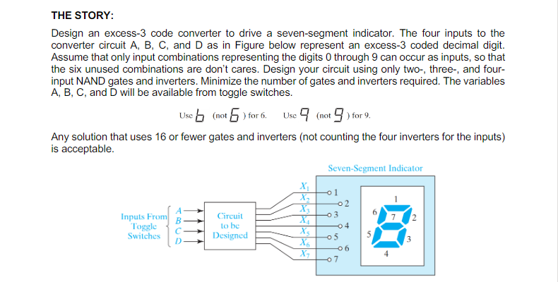
 Design an excess-3 code converter to drive a seven-segment indicator. The four inputs to the converter circuit A, B, C, and Dasin Figure belowrepresent an excess-3 coded decimal digit. Assume that only input combinations representing the digits 0 through 9 can occur as inputs, so that the six unused combinations are don’tcares. Design your circuit using only two-, three-, and four-input NAND gates and inverters. Minimize the number of gates and invertersrequired.ThevariablesA,B,C,and Dwill be availablefromtoggle switches.
Design an excess-3 code converter to drive a seven-segment indicator

4. Design a combinational circuit for a BCD to seven-segment code converter that will input a...
 4. Design a combinational circuit for a BCD to seven-segment code converter that will input a BCD number and output t on a seven segment common- anode display. The code converter will only display the number 8. Thoe converter wil turn the display OFF for all other valid BCD digits except digit 9 which will never occur. Draw a schematic. Show all steps clearly.
Write VHDL code for a BCD-to-seven segment LED display converter with four inputs, h3-h0, representing a...
Write VHDL code for a BCD-to-seven segment LED display converter with four inputs, h3-h0, representing a single decimal digit, and a seven-bit output suitable for driving a seven segment LED display on the Altera DE1 board. Refer to the textbook on the sample codes. Do not just simply copy the codes. Please use negative logic for the seven segment LED display, i.e., use expression such as when "0000" =>leds<="0000001", as the DE1 board uses such logic for the LEDs.
3. Design a combinational circuit with inputs a, b, c, d and outputs w, z, y, z, where the input ...
 1- Please answer all the question
2- with clear handwriting
Thank you,
3. Design a combinational circuit with inputs a, b, c, d and outputs w, z, y, z, where the input and output both represent a signed numbers (2s complement). The output is 7 less than the input, if the input is positive, or zero. If the input is negative, the output is 3 greater than the input. 7. Use the Boolean functions developed in problem #3 to create...
1- Please answer all the question
2- with clear handwriting
Thank you,
3. Design a combinational circuit with inputs a, b, c, d and outputs w, z, y, z, where the input and output both represent a signed numbers (2s complement). The output is 7 less than the input, if the input is positive, or zero. If the input is negative, the output is 3 greater than the input. 7. Use the Boolean functions developed in problem #3 to create...
Design and implement a combinational circuit with four inputs w,x, y and z and four outputs A, B ,C and D using CMOS transistors. When the binary input is 0, 1, 2,3,4,5,6 or 7 the binary output is fi...
Design and implement a combinational circuit with four inputs w,x, y and z and four outputs A, B ,C and D using CMOS transistors. When the binary input is 0, 1, 2,3,4,5,6 or 7 the binary output is five greater than the input. When the binary input is 8,,10,11,12,13,14 or 15 the binary output is seven less than the input. for question (a) find the troth table for the inputs (ABCD) then implement using K-map to find the equations to...
1. a. Design and implement a combinational circuit with three inputs w, x, and y and three outputs A, B and C using CMOS transistors. When the binary input is 0, 1, 2 or 3 the binary output is three g...
 1.
a. Design and implement a combinational circuit with three
inputs w, x, and y and three outputs A, B and C using CMOS
transistors. When the binary input is 0, 1, 2 or 3 the binary
output is three greater than the input. When the binary input is 4,
5, 6 or 7 the binary output is three less than the input.
b. from the part (a) , Draw the mask layout with Ln = Lp= 0.6
μm, Wn=...
1.
a. Design and implement a combinational circuit with three
inputs w, x, and y and three outputs A, B and C using CMOS
transistors. When the binary input is 0, 1, 2 or 3 the binary
output is three greater than the input. When the binary input is 4,
5, 6 or 7 the binary output is three less than the input.
b. from the part (a) , Draw the mask layout with Ln = Lp= 0.6
μm, Wn=...
 can someone help me solve this please
Design an excess-3 code converter to drive a seven-segment indicator. The four inputs to the converter circuit represent an excess-3 coded decimal digit. Assume that only input combinations representing the digits 0 through 9 can occur as inputs, so that the six unused combinations are don't-cares. Implement the circuits using Decoder(s) (active low) and any necessary external gates and a separate solution using Multiplexer(S) and any necessary external gates Please specify the integrated...
can someone help me solve this please
Design an excess-3 code converter to drive a seven-segment indicator. The four inputs to the converter circuit represent an excess-3 coded decimal digit. Assume that only input combinations representing the digits 0 through 9 can occur as inputs, so that the six unused combinations are don't-cares. Implement the circuits using Decoder(s) (active low) and any necessary external gates and a separate solution using Multiplexer(S) and any necessary external gates Please specify the integrated...
 4. Design a combinational circuit for a BCD to seven-segment code converter that will input a BCD number and output t on a seven segment common- anode display. The code converter will only display the number 8. Thoe converter wil turn the display OFF for all other valid BCD digits except digit 9 which will never occur. Draw a schematic. Show all steps clearly.
 1- Please answer all the question
2- with clear handwriting
Thank you,
3. Design a combinational circuit with inputs a, b, c, d and outputs w, z, y, z, where the input and output both represent a signed numbers (2s complement). The output is 7 less than the input, if the input is positive, or zero. If the input is negative, the output is 3 greater than the input. 7. Use the Boolean functions developed in problem #3 to create...
1- Please answer all the question
2- with clear handwriting
Thank you,
3. Design a combinational circuit with inputs a, b, c, d and outputs w, z, y, z, where the input and output both represent a signed numbers (2s complement). The output is 7 less than the input, if the input is positive, or zero. If the input is negative, the output is 3 greater than the input. 7. Use the Boolean functions developed in problem #3 to create...
 1.
a. Design and implement a combinational circuit with three
inputs w, x, and y and three outputs A, B and C using CMOS
transistors. When the binary input is 0, 1, 2 or 3 the binary
output is three greater than the input. When the binary input is 4,
5, 6 or 7 the binary output is three less than the input.
b. from the part (a) , Draw the mask layout with Ln = Lp= 0.6
μm, Wn=...
1.
a. Design and implement a combinational circuit with three
inputs w, x, and y and three outputs A, B and C using CMOS
transistors. When the binary input is 0, 1, 2 or 3 the binary
output is three greater than the input. When the binary input is 4,
5, 6 or 7 the binary output is three less than the input.
b. from the part (a) , Draw the mask layout with Ln = Lp= 0.6
μm, Wn=...
Most questions answered within 3 hours.
-
Calculate the pH of each of the following solutions.
0.50 M HBr
3.1×10⁻⁴ M KOH
4.2×10⁻⁵...
asked 2 hours ago -
For the year ended December 31, Depot Max’s cost of merchandise
sold was $85,600. Inventory at the...
asked 2 hours ago -
Week 10 - Professional Memo Assignment
Professional Memo Assignment
Your mission for this week, should you...
asked 2 hours ago -
Write a Python program that stores the data for each
player on the team, and it...
asked 2 hours ago -
In
the last 3 months, mike never knows when he is going to get his
allowance...
asked 2 hours ago -
Is Ca(OH)2 a Bronsted base, Lewis base, or both? Why?
asked 2 hours ago -
1A- Why don’t voters complain about U.S. tariffs on imported
sugar?
Because sugar is only a...
asked 2 hours ago -
Cash Payback Period
Primera Banco is evaluating two capital investment proposals for
a drive-up ATM kiosk,...
asked 2 hours ago -
Create a button in Swift (Xcode) that will create a charge,
create a charge using Stripe's...
asked 2 hours ago -
The reaction rate of CO and NO2 in the reaction
CO(g) + NO2(g) → CO2(g) +...
asked 2 hours ago -
Imagine that a chemist puts 6.40 mol each of
C3H8 and O2 in a 1.00-L container...
asked 3 hours ago -
How much money should be invested today in order to have $8340
at the end of...
asked 3 hours ago