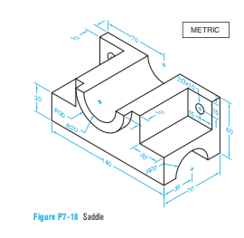
Given the isometric view of the object (Figure 7-18) in page 245 in your text
Draw front, top and right side views. Use an appropriate scale to fit all three views in one page in landscape orientation. Show all dimensions. Show all hidden and center lines using AutoCAD.
Homework Answers

Add Answer to:
Given the isometric view of the object (Figure 7-18) in page 245
in your text
Draw...
Given the isometric view of the object (Figure 7-13) in page 243in your textDraw...
 Given the isometric view of the object (Figure 7-13) in page 243
in your textDraw front, top and right side views.
Use an appropriate scale to fit all three views in one page in
landscape orientation. Show all dimensions. Show all hidden and center lines using AutoCAD.
Given the isometric view of the object (Figure 7-13) in page 243
in your textDraw front, top and right side views.
Use an appropriate scale to fit all three views in one page in
landscape orientation. Show all dimensions. Show all hidden and center lines using AutoCAD.
please use the graphic paper Sketch the ISOMETRIC view of the object. The given TOP, FRONT...
 please use the graphic paper
Sketch the ISOMETRIC view of the object. The given TOP, FRONT and RIGHT SIDE views are complete. Use point "O" for orientation. TOP RIGHT SIDE FRONT
please use the graphic paper
Sketch the ISOMETRIC view of the object. The given TOP, FRONT and RIGHT SIDE views are complete. Use point "O" for orientation. TOP RIGHT SIDE FRONT
STUDENT NUMBER Front, top, and left side views of the object are given. Sketch an isometric...
 STUDENT NUMBER Front, top, and left side views of the object are given. Sketch an isometric view of the object. This view must show the object as seen in the direction of the arrow. Draw using I I scale.
DRAWING -1: Draw the following views to describe the object in Figure D a sectional FRONT view on...
 DRAWING -1: Draw the following views to describe the object in Figure D a sectional FRONT view on A-A, - a SIDE view from B, -a TOP view DIMENSIONS ARE IN MILLIMETRES PLOT THE DRAWING ON A SCALE OF 1: M30 x2 2 x φ10 R12 R 6 25 20 638
DRAWING -1: Draw the following views to describe the object in Figure D a sectional FRONT view on A-A, - a SIDE view from B, -a TOP view DIMENSIONS...
DRAWING -1: Draw the following views to describe the object in Figure D a sectional FRONT view on A-A, - a SIDE view from B, -a TOP view DIMENSIONS ARE IN MILLIMETRES PLOT THE DRAWING ON A SCALE OF 1: M30 x2 2 x φ10 R12 R 6 25 20 638
DRAWING -1: Draw the following views to describe the object in Figure D a sectional FRONT view on A-A, - a SIDE view from B, -a TOP view DIMENSIONS...
2D Slider Autocad drawing Assume the 120mm x 250mm side is the FRONT. Also create TOP,...
 2D Slider Autocad drawing
Assume the 120mm x 250mm side is the FRONT. Also create
TOP, BOTTOM, LEFT and RIGHT side views.
1. The right side of Slider is not given but should end
up being between 25-30 mm high.
2. Both of the 20 mm diameter holes go all the way
through.
3. The slot on the left side also goes all the way
through.
Include all the appropriate features and line types as
needed. Continuous, hidden, center. Make...
2D Slider Autocad drawing
Assume the 120mm x 250mm side is the FRONT. Also create
TOP, BOTTOM, LEFT and RIGHT side views.
1. The right side of Slider is not given but should end
up being between 25-30 mm high.
2. Both of the 20 mm diameter holes go all the way
through.
3. The slot on the left side also goes all the way
through.
Include all the appropriate features and line types as
needed. Continuous, hidden, center. Make...
Draw the necessary orthographic views to describe the object in Figure D2. The drawing shall incl...
 Draw the necessary orthographic views to describe the object in Figure D2. The drawing shall include the following views: a HALF SECTIONAL FRONT view from A a SIDE view from B ALL DIMENSIONS ARE IN MILLIMETRES PLOT THE DRAWING ON A SCALE OF 1:2. 58 32 0132 0115 5116 φ100 ф86 R4 φ64 010 THRU R3 070 ALL UNMARKED RADIIR 30 050 THRU в/
Draw the necessary orthographic views to describe the object in Figure D2. The drawing shall include...
Draw the necessary orthographic views to describe the object in Figure D2. The drawing shall include the following views: a HALF SECTIONAL FRONT view from A a SIDE view from B ALL DIMENSIONS ARE IN MILLIMETRES PLOT THE DRAWING ON A SCALE OF 1:2. 58 32 0132 0115 5116 φ100 ф86 R4 φ64 010 THRU R3 070 ALL UNMARKED RADIIR 30 050 THRU в/
Draw the necessary orthographic views to describe the object in Figure D2. The drawing shall include...
Please drawing the front view, top view and side view of this drafing tools. + on the top view, d...
 Please drawing the front view, top view and side view of this
drafing tools.
+ on the top view, draw a cutting plane AA’ to draw a section
view please.
+ Please drawing the isometric Pictorial drawing also.
Thank you!
t 1305-FINAL PROJECT B" You are showed a machined part, and you are to messure that part using e caliper Then you wil ransfer the neasurement into hand drawings with drafting tooks that you will be creating # for the...
Please drawing the front view, top view and side view of this
drafing tools.
+ on the top view, draw a cutting plane AA’ to draw a section
view please.
+ Please drawing the isometric Pictorial drawing also.
Thank you!
t 1305-FINAL PROJECT B" You are showed a machined part, and you are to messure that part using e caliper Then you wil ransfer the neasurement into hand drawings with drafting tooks that you will be creating # for the...
Use the guidelines provided & neatly letter the following statement using INCLINED lettering: (10 pts) PENCIL...
Use the guidelines provided & neatly letter the following statement using INCLINED lettering: (10 pts) PENCIL LETTERING SHOULD BE DONE WITH A FAIRLY SOFT SHARP PENCIL YOUR LETTERING MUST BE CLEAN-CUT AND UNIFORM. 2. Measure each line and write your answer in the space provided. (5 pts EACH) a. Metric 1:125 (meters) ├──────────────────────────┤ Answer: __________ b. Engineer’s 1"=3' ├──────────────────────────────┤ Answer: __________ c. Engineer’s 1"=400' ├─────────────────────────────────┤ Answer: __________ d. Architect’s 3/32" = 1'-0" ├───────────────────────────────────┤ Answer: __________ ...
 Given the isometric view of the object (Figure 7-13) in page 243
in your textDraw front, top and right side views.
Use an appropriate scale to fit all three views in one page in
landscape orientation. Show all dimensions. Show all hidden and center lines using AutoCAD.
Given the isometric view of the object (Figure 7-13) in page 243
in your textDraw front, top and right side views.
Use an appropriate scale to fit all three views in one page in
landscape orientation. Show all dimensions. Show all hidden and center lines using AutoCAD.
 please use the graphic paper
Sketch the ISOMETRIC view of the object. The given TOP, FRONT and RIGHT SIDE views are complete. Use point "O" for orientation. TOP RIGHT SIDE FRONT
please use the graphic paper
Sketch the ISOMETRIC view of the object. The given TOP, FRONT and RIGHT SIDE views are complete. Use point "O" for orientation. TOP RIGHT SIDE FRONT
 STUDENT NUMBER Front, top, and left side views of the object are given. Sketch an isometric view of the object. This view must show the object as seen in the direction of the arrow. Draw using I I scale.
 DRAWING -1: Draw the following views to describe the object in Figure D a sectional FRONT view on A-A, - a SIDE view from B, -a TOP view DIMENSIONS ARE IN MILLIMETRES PLOT THE DRAWING ON A SCALE OF 1: M30 x2 2 x φ10 R12 R 6 25 20 638
DRAWING -1: Draw the following views to describe the object in Figure D a sectional FRONT view on A-A, - a SIDE view from B, -a TOP view DIMENSIONS...
DRAWING -1: Draw the following views to describe the object in Figure D a sectional FRONT view on A-A, - a SIDE view from B, -a TOP view DIMENSIONS ARE IN MILLIMETRES PLOT THE DRAWING ON A SCALE OF 1: M30 x2 2 x φ10 R12 R 6 25 20 638
DRAWING -1: Draw the following views to describe the object in Figure D a sectional FRONT view on A-A, - a SIDE view from B, -a TOP view DIMENSIONS...
 2D Slider Autocad drawing
Assume the 120mm x 250mm side is the FRONT. Also create
TOP, BOTTOM, LEFT and RIGHT side views.
1. The right side of Slider is not given but should end
up being between 25-30 mm high.
2. Both of the 20 mm diameter holes go all the way
through.
3. The slot on the left side also goes all the way
through.
Include all the appropriate features and line types as
needed. Continuous, hidden, center. Make...
2D Slider Autocad drawing
Assume the 120mm x 250mm side is the FRONT. Also create
TOP, BOTTOM, LEFT and RIGHT side views.
1. The right side of Slider is not given but should end
up being between 25-30 mm high.
2. Both of the 20 mm diameter holes go all the way
through.
3. The slot on the left side also goes all the way
through.
Include all the appropriate features and line types as
needed. Continuous, hidden, center. Make...
 Draw the necessary orthographic views to describe the object in Figure D2. The drawing shall include the following views: a HALF SECTIONAL FRONT view from A a SIDE view from B ALL DIMENSIONS ARE IN MILLIMETRES PLOT THE DRAWING ON A SCALE OF 1:2. 58 32 0132 0115 5116 φ100 ф86 R4 φ64 010 THRU R3 070 ALL UNMARKED RADIIR 30 050 THRU в/
Draw the necessary orthographic views to describe the object in Figure D2. The drawing shall include...
Draw the necessary orthographic views to describe the object in Figure D2. The drawing shall include the following views: a HALF SECTIONAL FRONT view from A a SIDE view from B ALL DIMENSIONS ARE IN MILLIMETRES PLOT THE DRAWING ON A SCALE OF 1:2. 58 32 0132 0115 5116 φ100 ф86 R4 φ64 010 THRU R3 070 ALL UNMARKED RADIIR 30 050 THRU в/
Draw the necessary orthographic views to describe the object in Figure D2. The drawing shall include...
 Please drawing the front view, top view and side view of this
drafing tools.
+ on the top view, draw a cutting plane AA’ to draw a section
view please.
+ Please drawing the isometric Pictorial drawing also.
Thank you!
t 1305-FINAL PROJECT B" You are showed a machined part, and you are to messure that part using e caliper Then you wil ransfer the neasurement into hand drawings with drafting tooks that you will be creating # for the...
Please drawing the front view, top view and side view of this
drafing tools.
+ on the top view, draw a cutting plane AA’ to draw a section
view please.
+ Please drawing the isometric Pictorial drawing also.
Thank you!
t 1305-FINAL PROJECT B" You are showed a machined part, and you are to messure that part using e caliper Then you wil ransfer the neasurement into hand drawings with drafting tooks that you will be creating # for the...
Most questions answered within 3 hours.
-
Hello! I was wondering if I could have some help?
If the vapor pressure of carvone...
asked 6 minutes ago -
An economist wants to estimate the mean per capita income (in
thousands of dollars) for a...
asked 25 minutes ago -
What would be the input/output characteristic of a circuit
obtained by putting two of your 2's-complementers...
asked 24 minutes ago -
In Drosophila, the transition from the syncytial blastoderm
stage to the cellular blastoderm stage is a...
asked 53 minutes ago -
Project management question:
Name 3 different types of resources (hint: humans are one
type)
asked 1 hour ago -
Consider the following reaction: C 2H 2( g) + 2H 2( g) C 2H 6(
g)...
asked 1 hour ago -
Consider a 1.0 L buffer containing 0.092 mol L-1 HCOOH and 0.100
mol L-1 HCOO-. What...
asked 1 hour ago -
Koch Realty has owned a vacant land with a FMV of
$775,000 and an adjusted basis...
asked 1 hour ago -
It is estimated 29% of all adults in United States invest in
stocks and that 85%...
asked 1 hour ago -
What does a 2-sided p value of 0.04 mean? (I am not asking if it
is...
asked 1 hour ago -
A parallel-plate capacitor is made from two aluminum-foil
sheets, each 7.8 cmcm wide and 5.1 mmlong....
asked 1 hour ago -
1. why is toluene a stronger nucleophile than benzene?
2.why is phenol a stronger nucleophile than...
asked 2 hours ago