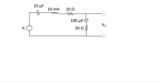
Replace the 100uF capacitor with a 100mH inductor. Then write down the transfer function for the following filter circuit. Ignore polarity signs on the capacitors.
Homework Answers


Add Answer to:
Replace the 100uF capacitor with a 100mH
inductor. Then write down the transfer function for the...
6) (a) Derive an expression for the transfer function H(s)- Vofs)Vi(s) of the circuit in Figure...
 6) (a) Derive an expression for the transfer function H(s)- Vofs)Vi(s) of the circuit in Figure 4 10 marks Vi(t) 1 Figure 4 (b) If the inductor value is 100 ?? and the capacitor value is 1 ?F calculate the value of the resistor required to ensure that the response of the circuit is critically px. (5 marks)
Find the transfer function between the output inductor voltage vl(t) and input voltage v(t) for the...
 Find the transfer function between the output inductor voltage vl(t) and input voltage v(t) for the following system? R v(t) llll vi(t) iſt)
By looking at the RLC circuit, determine which filter it is and explain. Also write down transfer function for each RLC...
 By looking at the RLC circuit, determine which filter it is and
explain. Also write down transfer function for each RLC circuit.
(use
to express the function and find relation between and
)
s'ζ, wo We were unable to transcribe this imageWe were unable to transcribe this imageout out out
s'ζ, wo
out out out
By looking at the RLC circuit, determine which filter it is and
explain. Also write down transfer function for each RLC circuit.
(use
to express the function and find relation between and
)
s'ζ, wo We were unable to transcribe this imageWe were unable to transcribe this imageout out out
s'ζ, wo
out out out
Find the transfer function between the output inductor voltage vl(t) and input voltage v(t) for the...
 Find the transfer function between the output inductor voltage vl(t) and input voltage v(t) for the following system? R w + v(t) + 0000 vi(t) iſt)
please do part d only: Replace R1 with a series combination of R1 and a capacitor. Assume Vin = V0sinwt. determine the magnitude of vout/v0 as a function of w and sketch, noting values at critical r...
 please do part d only: Replace R1 with a series combination of
R1 and a capacitor. Assume Vin = V0sinwt. determine the magnitude
of vout/v0 as a function of w and sketch, noting values at critical
regions of the graph. what kind of circuit is this?
1. [50 points total] Consider the circuit model for a non- inverting operational amplifier circuit: Vin a. [10 points] Identify all of the nodes in the circuit diagram -how many are there? How many...
please do part d only: Replace R1 with a series combination of
R1 and a capacitor. Assume Vin = V0sinwt. determine the magnitude
of vout/v0 as a function of w and sketch, noting values at critical
regions of the graph. what kind of circuit is this?
1. [50 points total] Consider the circuit model for a non- inverting operational amplifier circuit: Vin a. [10 points] Identify all of the nodes in the circuit diagram -how many are there? How many...
2. In the circuit below all resistors are 1-ohm and the value of the inductor is 1H a. Determine the transfer function 'e in the frequency domain. b. If Vi(t) = 3 n= 1-sin (nrt) determine vo(t) c...
 2. In the circuit below all resistors are 1-ohm and the value of the inductor is 1H a. Determine the transfer function 'e in the frequency domain. b. If Vi(t) = 3 n= 1-sin (nrt) determine vo(t) c. Determine the input normalized power 1 나 1 V.
2. In the circuit below all resistors are 1-ohm and the value of the inductor is 1H a. Determine the transfer function 'e in the frequency domain. b. If Vi(t) = 3 n=...
2. In the circuit below all resistors are 1-ohm and the value of the inductor is 1H a. Determine the transfer function 'e in the frequency domain. b. If Vi(t) = 3 n= 1-sin (nrt) determine vo(t) c. Determine the input normalized power 1 나 1 V.
2. In the circuit below all resistors are 1-ohm and the value of the inductor is 1H a. Determine the transfer function 'e in the frequency domain. b. If Vi(t) = 3 n=...
4. This problem explores the transfer of energy in an LC circuit. The capacitor in the...
 4. This problem explores the transfer of energy in an LC circuit. The capacitor in the circuit shown below is initially charged with a charge Qo. Write down the equations for energy stored in a capacitor and energy stored in an inductor. What is the total energy in this system in terms of charge and current? a. 00000 b. Rewrite your answer in part a, but plug in i = Because there is no resistor in this circuit, the system...
Q1. For the filter circuit shown below, (5 marks) Vo(s) a) Find the transfer function, G(s)...
 Q1. For the filter circuit shown below, (5 marks) Vo(s) a) Find the transfer function, G(s) and the type of the filter. (4 marks) Vi(s)' b) Find the initial and final values of vo(t) if vi(t) = 2u(t). (1 marks) 10 k12 w 6 тн 0000 v;(1) 5 k92 2 mF
2. An ideal inductor with inductance L and an ideal capacitor with capacitance C are connected...
 2. An ideal inductor with inductance L and an ideal capacitor with capacitance C are connected in series with a battery with voltage and a switch. Att 0 the switch is closed. In this scenario, the charge on the capacitor will oscillate sinusoidally but will have a DC offset. It can be expressed in general using three parameters (Ao, Ai, and A2) with the following. q(t) AA cos(ut)A2 sin(ut) where wis the natural frequency of the circuit. Note also that...
i)Derive (showing detailed steps) the transfer function T(s)? put T(s) in the standard format and hence show that ? ii)show that m=4Q and w=2q/rc Let R=10k Ω , compute the value of the capacitor C in...
 i)Derive (showing detailed steps) the transfer function T(s)?
put T(s) in the standard format and hence
show that ?
ii)show that m=4Q and w=2q/rc
Let R=10k Ω , compute the value of the
capacitor C in order to obtain a second Butterworth (i.e. maximally
flat) filter
with ωp=10 rad/seconds and Amax=0.5 dB.?
ion 1 (12 Mar Consider the given Single-Amplifier Biquadratic (SAB) active low-pass filter circuit (to the right) i. Derive (showing detailed steps) the transfer function T(s)Vofthis circuit, please...
i)Derive (showing detailed steps) the transfer function T(s)?
put T(s) in the standard format and hence
show that ?
ii)show that m=4Q and w=2q/rc
Let R=10k Ω , compute the value of the
capacitor C in order to obtain a second Butterworth (i.e. maximally
flat) filter
with ωp=10 rad/seconds and Amax=0.5 dB.?
ion 1 (12 Mar Consider the given Single-Amplifier Biquadratic (SAB) active low-pass filter circuit (to the right) i. Derive (showing detailed steps) the transfer function T(s)Vofthis circuit, please...
 6) (a) Derive an expression for the transfer function H(s)- Vofs)Vi(s) of the circuit in Figure 4 10 marks Vi(t) 1 Figure 4 (b) If the inductor value is 100 ?? and the capacitor value is 1 ?F calculate the value of the resistor required to ensure that the response of the circuit is critically px. (5 marks)
 Find the transfer function between the output inductor voltage vl(t) and input voltage v(t) for the following system? R v(t) llll vi(t) iſt)
 By looking at the RLC circuit, determine which filter it is and
explain. Also write down transfer function for each RLC circuit.
(use
to express the function and find relation between and
)
s'ζ, wo We were unable to transcribe this imageWe were unable to transcribe this imageout out out
s'ζ, wo
out out out
By looking at the RLC circuit, determine which filter it is and
explain. Also write down transfer function for each RLC circuit.
(use
to express the function and find relation between and
)
s'ζ, wo We were unable to transcribe this imageWe were unable to transcribe this imageout out out
s'ζ, wo
out out out
 Find the transfer function between the output inductor voltage vl(t) and input voltage v(t) for the following system? R w + v(t) + 0000 vi(t) iſt)
 please do part d only: Replace R1 with a series combination of
R1 and a capacitor. Assume Vin = V0sinwt. determine the magnitude
of vout/v0 as a function of w and sketch, noting values at critical
regions of the graph. what kind of circuit is this?
1. [50 points total] Consider the circuit model for a non- inverting operational amplifier circuit: Vin a. [10 points] Identify all of the nodes in the circuit diagram -how many are there? How many...
please do part d only: Replace R1 with a series combination of
R1 and a capacitor. Assume Vin = V0sinwt. determine the magnitude
of vout/v0 as a function of w and sketch, noting values at critical
regions of the graph. what kind of circuit is this?
1. [50 points total] Consider the circuit model for a non- inverting operational amplifier circuit: Vin a. [10 points] Identify all of the nodes in the circuit diagram -how many are there? How many...
 2. In the circuit below all resistors are 1-ohm and the value of the inductor is 1H a. Determine the transfer function 'e in the frequency domain. b. If Vi(t) = 3 n= 1-sin (nrt) determine vo(t) c. Determine the input normalized power 1 나 1 V.
2. In the circuit below all resistors are 1-ohm and the value of the inductor is 1H a. Determine the transfer function 'e in the frequency domain. b. If Vi(t) = 3 n=...
2. In the circuit below all resistors are 1-ohm and the value of the inductor is 1H a. Determine the transfer function 'e in the frequency domain. b. If Vi(t) = 3 n= 1-sin (nrt) determine vo(t) c. Determine the input normalized power 1 나 1 V.
2. In the circuit below all resistors are 1-ohm and the value of the inductor is 1H a. Determine the transfer function 'e in the frequency domain. b. If Vi(t) = 3 n=...
 4. This problem explores the transfer of energy in an LC circuit. The capacitor in the circuit shown below is initially charged with a charge Qo. Write down the equations for energy stored in a capacitor and energy stored in an inductor. What is the total energy in this system in terms of charge and current? a. 00000 b. Rewrite your answer in part a, but plug in i = Because there is no resistor in this circuit, the system...
 Q1. For the filter circuit shown below, (5 marks) Vo(s) a) Find the transfer function, G(s) and the type of the filter. (4 marks) Vi(s)' b) Find the initial and final values of vo(t) if vi(t) = 2u(t). (1 marks) 10 k12 w 6 тн 0000 v;(1) 5 k92 2 mF
 2. An ideal inductor with inductance L and an ideal capacitor with capacitance C are connected in series with a battery with voltage and a switch. Att 0 the switch is closed. In this scenario, the charge on the capacitor will oscillate sinusoidally but will have a DC offset. It can be expressed in general using three parameters (Ao, Ai, and A2) with the following. q(t) AA cos(ut)A2 sin(ut) where wis the natural frequency of the circuit. Note also that...
 i)Derive (showing detailed steps) the transfer function T(s)?
put T(s) in the standard format and hence
show that ?
ii)show that m=4Q and w=2q/rc
Let R=10k Ω , compute the value of the
capacitor C in order to obtain a second Butterworth (i.e. maximally
flat) filter
with ωp=10 rad/seconds and Amax=0.5 dB.?
ion 1 (12 Mar Consider the given Single-Amplifier Biquadratic (SAB) active low-pass filter circuit (to the right) i. Derive (showing detailed steps) the transfer function T(s)Vofthis circuit, please...
i)Derive (showing detailed steps) the transfer function T(s)?
put T(s) in the standard format and hence
show that ?
ii)show that m=4Q and w=2q/rc
Let R=10k Ω , compute the value of the
capacitor C in order to obtain a second Butterworth (i.e. maximally
flat) filter
with ωp=10 rad/seconds and Amax=0.5 dB.?
ion 1 (12 Mar Consider the given Single-Amplifier Biquadratic (SAB) active low-pass filter circuit (to the right) i. Derive (showing detailed steps) the transfer function T(s)Vofthis circuit, please...
Most questions answered within 3 hours.
-
Do not neglect the old for the new. The existing business must
not lose priority simply...
asked 1 hour ago -
Kylie is a single mom with two dependent children,
Tanner, age 7 and Olivia, age 11....
asked 2 hours ago -
Phosphorous + bromine = phosphorous tribromide. If 35.0 g of
bromine are reacted and 27.9 grams...
asked 3 hours ago -
Derive the long wavelength limit of the Planck energy density
distribution
asked 3 hours ago -
Calculate the pH of each of the following solutions.
0.50 M HBr
3.1×10⁻⁴ M KOH
4.2×10⁻⁵...
asked 7 hours ago -
For the year ended December 31, Depot Max’s cost of merchandise
sold was $85,600. Inventory at the...
asked 7 hours ago -
Week 10 - Professional Memo Assignment
Professional Memo Assignment
Your mission for this week, should you...
asked 7 hours ago -
Write a Python program that stores the data for each
player on the team, and it...
asked 7 hours ago -
In
the last 3 months, mike never knows when he is going to get his
allowance...
asked 7 hours ago -
Is Ca(OH)2 a Bronsted base, Lewis base, or both? Why?
asked 7 hours ago -
1A- Why don’t voters complain about U.S. tariffs on imported
sugar?
Because sugar is only a...
asked 7 hours ago -
Cash Payback Period
Primera Banco is evaluating two capital investment proposals for
a drive-up ATM kiosk,...
asked 7 hours ago