
Homework Answers

Add Answer to:
1. Design the following series RLC filter (find values of R and L) with a quality...
1. Design a parallel RLC bandpass filter, derive the transfer function H(s). Compute the center frequency, Wo. Calculate the cutoff frequencies Wej and Wc2, the bandwidth ß, and quality factor, Q. Co...
 1. Design a parallel RLC bandpass filter, derive the transfer function H(s). Compute the center frequency, Wo. Calculate the cutoff frequencies Wej and Wc2, the bandwidth ß, and quality factor, Q. Compute values for R and L to yield a bandpass filter with a center frequency of 5kHz and a bandwidth of 200Hz, using a 10nF capacitor. (25 points)
1. Design a parallel RLC bandpass filter, derive the transfer function H(s). Compute the center frequency, Wo. Calculate the cutoff frequencies...
1. Design a parallel RLC bandpass filter, derive the transfer function H(s). Compute the center frequency, Wo. Calculate the cutoff frequencies Wej and Wc2, the bandwidth ß, and quality factor, Q. Compute values for R and L to yield a bandpass filter with a center frequency of 5kHz and a bandwidth of 200Hz, using a 10nF capacitor. (25 points)
1. Design a parallel RLC bandpass filter, derive the transfer function H(s). Compute the center frequency, Wo. Calculate the cutoff frequencies...
Problem 4 Use a 5 nF capacitor to design a series RLC bandpass filter. The center...
 Problem 4 Use a 5 nF capacitor to design a series RLC bandpass filter. The center frequency the filter is 8 kHz, and the quality factor is 1.5. Part A Specify the value of L. View Available Hint(s) EVO AQH vec ? L = 0.079 ml Submit Previous Answers * Incorrect; Try Again; 8 attempts remaining Part B Specify the value of R. 10 AEDIf vec ? R = k12 Submit Request Answer Problem 4 Use a 5 nF capacitor...
DESIGN PROBLEM MULTISIN 14.20 Use a 5 nF capacitor to design a series RLC band- pass...
 DESIGN PROBLEM MULTISIN 14.20 Use a 5 nF capacitor to design a series RLC band- pass filter, as shown at the top of Fig. 14.27. The cen- PSPICE ter frequency of the filter is 8 kHz, and the quality factor is 2. a) Specify the values of R and L. b) What is the lower cutoff frequency in kilohertz? c) What is the upper cutoff frequency in kilohertz? d) What is the bandwidth of the filter in kilohertz? p rin...
Please make it clear handwriting. I will leave positive feedback For a series RLC bandreject filter...
 Please make it clear handwriting. I will leave
positive feedback
For a series RLC bandreject filter with center frequency 2.4 kHz, quality factor 3, and with a 200 nF capacitor, R SL V/8) V.() 1/C a. (15) Determine the component values and units for R, L and the two cutoff frequencies Wc1, Wc2 R= L = Wc1 = Wc2 b. (15) Calculate the amplitude frequency response and plot it using linear scales. C. (20) Assume now that an external load,...
Please make it clear handwriting. I will leave
positive feedback
For a series RLC bandreject filter with center frequency 2.4 kHz, quality factor 3, and with a 200 nF capacitor, R SL V/8) V.() 1/C a. (15) Determine the component values and units for R, L and the two cutoff frequencies Wc1, Wc2 R= L = Wc1 = Wc2 b. (15) Calculate the amplitude frequency response and plot it using linear scales. C. (20) Assume now that an external load,...
pls i want as fast as possible Q4 (20 pts) Design a series RLC band pass...
 pls i want as fast as possible
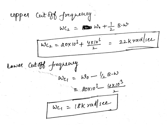
Q4 (20 pts) Design a series RLC band pass filter as shown below, with low frequency cut-off at W = 100 rad/sec and high frequency cut-off at WH=10 krad /sec. (4 pts) a) Determine the center frequency wo and the bandwidth B (10 pts) b) Choose L-100 mH and calculate the values of R and C (6 pts) c) Find the magnitude of H(jw)= Vo / V, and evaluate it at www с...
pls i want as fast as possible
Q4 (20 pts) Design a series RLC band pass filter as shown below, with low frequency cut-off at W = 100 rad/sec and high frequency cut-off at WH=10 krad /sec. (4 pts) a) Determine the center frequency wo and the bandwidth B (10 pts) b) Choose L-100 mH and calculate the values of R and C (6 pts) c) Find the magnitude of H(jw)= Vo / V, and evaluate it at www с...
PartA Design a series RLC bandpass filter using only three components from Appendix H that comes ...
 PartA Design a series RLC bandpass filter using only three components from Appendix H that comes closest to the filter with a quality factor of 2 and a center frequency of 8 kHz Choose L 10 mH. Then, what is the value of C? vec AF Submit Request Answen Part B What is the value of R? vec Problem 14.28 Part Design a series RLC bandpass filter using only three components from Appendix H that comes closest to the filter...
answer fast 2- Design an RLC Band Reject filter with a lower cutoff frequency of 2...
 answer fast
2- Design an RLC Band Reject filter with a lower cutoff frequency of 2 kHz and an upper cutoff frequency of 2.1 kHz. Consider a capacitor C = 3.7nF and calculate L, C, and Q. a) Give the Transfer function of this filter. b) Find the central frequency f., the bandwidth (BW) in Hz, and the quality factor (Q). c) Sketch the frequency response of this filter only magnitude.
answer fast
2- Design an RLC Band Reject filter with a lower cutoff frequency of 2 kHz and an upper cutoff frequency of 2.1 kHz. Consider a capacitor C = 3.7nF and calculate L, C, and Q. a) Give the Transfer function of this filter. b) Find the central frequency f., the bandwidth (BW) in Hz, and the quality factor (Q). c) Sketch the frequency response of this filter only magnitude.
The center frequency is not given. I believe that it must be find based on the body plot. Problem 6:The Bode plot for a passive series RLC bandpass filter is shown in Fig. 2. This filter was built...
 The center frequency is not given. I believe that it must be
find based on the body plot.
Problem 6:The Bode plot for a passive series RLC bandpass filter is shown in Fig. 2. This filter was built from a 10 μ F capacitor. What is the filter's center frequency, wo, and its quality factor,昱? If you wanted to double the filter's center frequency without changing its quality factor, using the same 10 pu F capacitor, then how would you...
The center frequency is not given. I believe that it must be
find based on the body plot.
Problem 6:The Bode plot for a passive series RLC bandpass filter is shown in Fig. 2. This filter was built from a 10 μ F capacitor. What is the filter's center frequency, wo, and its quality factor,昱? If you wanted to double the filter's center frequency without changing its quality factor, using the same 10 pu F capacitor, then how would you...
Learning Goal: To analyze and design a passive, second-order bandpass filter using a series RLC circuit....
 Learning Goal: To analyze and design a passive, second-order bandpass filter using a series RLC circuit. A bandpass filter is needed for an equalizer, a device that allows one to select the level of amplification of sounds within a specific frequency band while not affecting the sounds outside that band. The filter should block frequencies lower than 1.8 kHz and have a resonant frequency of 5.4 kHz A 3.2 AF capacitor and any needed resistors and inductors are available to...
Using an RLC circuit to design a band-reject filter, with the two cut off frequencies 40k...
Using an RLC circuit to design a band-reject filter, with the two cut off frequencies 40k and 90k Hz. Design the values of R, L, C, quality factor Q, and find the output terminals on the circuit.
 1. Design a parallel RLC bandpass filter, derive the transfer function H(s). Compute the center frequency, Wo. Calculate the cutoff frequencies Wej and Wc2, the bandwidth ß, and quality factor, Q. Compute values for R and L to yield a bandpass filter with a center frequency of 5kHz and a bandwidth of 200Hz, using a 10nF capacitor. (25 points)
1. Design a parallel RLC bandpass filter, derive the transfer function H(s). Compute the center frequency, Wo. Calculate the cutoff frequencies...
1. Design a parallel RLC bandpass filter, derive the transfer function H(s). Compute the center frequency, Wo. Calculate the cutoff frequencies Wej and Wc2, the bandwidth ß, and quality factor, Q. Compute values for R and L to yield a bandpass filter with a center frequency of 5kHz and a bandwidth of 200Hz, using a 10nF capacitor. (25 points)
1. Design a parallel RLC bandpass filter, derive the transfer function H(s). Compute the center frequency, Wo. Calculate the cutoff frequencies...
 Problem 4 Use a 5 nF capacitor to design a series RLC bandpass filter. The center frequency the filter is 8 kHz, and the quality factor is 1.5. Part A Specify the value of L. View Available Hint(s) EVO AQH vec ? L = 0.079 ml Submit Previous Answers * Incorrect; Try Again; 8 attempts remaining Part B Specify the value of R. 10 AEDIf vec ? R = k12 Submit Request Answer Problem 4 Use a 5 nF capacitor...
 DESIGN PROBLEM MULTISIN 14.20 Use a 5 nF capacitor to design a series RLC band- pass filter, as shown at the top of Fig. 14.27. The cen- PSPICE ter frequency of the filter is 8 kHz, and the quality factor is 2. a) Specify the values of R and L. b) What is the lower cutoff frequency in kilohertz? c) What is the upper cutoff frequency in kilohertz? d) What is the bandwidth of the filter in kilohertz? p rin...
 Please make it clear handwriting. I will leave
positive feedback
For a series RLC bandreject filter with center frequency 2.4 kHz, quality factor 3, and with a 200 nF capacitor, R SL V/8) V.() 1/C a. (15) Determine the component values and units for R, L and the two cutoff frequencies Wc1, Wc2 R= L = Wc1 = Wc2 b. (15) Calculate the amplitude frequency response and plot it using linear scales. C. (20) Assume now that an external load,...
Please make it clear handwriting. I will leave
positive feedback
For a series RLC bandreject filter with center frequency 2.4 kHz, quality factor 3, and with a 200 nF capacitor, R SL V/8) V.() 1/C a. (15) Determine the component values and units for R, L and the two cutoff frequencies Wc1, Wc2 R= L = Wc1 = Wc2 b. (15) Calculate the amplitude frequency response and plot it using linear scales. C. (20) Assume now that an external load,...
 pls i want as fast as possible
Q4 (20 pts) Design a series RLC band pass filter as shown below, with low frequency cut-off at W = 100 rad/sec and high frequency cut-off at WH=10 krad /sec. (4 pts) a) Determine the center frequency wo and the bandwidth B (10 pts) b) Choose L-100 mH and calculate the values of R and C (6 pts) c) Find the magnitude of H(jw)= Vo / V, and evaluate it at www с...
pls i want as fast as possible
Q4 (20 pts) Design a series RLC band pass filter as shown below, with low frequency cut-off at W = 100 rad/sec and high frequency cut-off at WH=10 krad /sec. (4 pts) a) Determine the center frequency wo and the bandwidth B (10 pts) b) Choose L-100 mH and calculate the values of R and C (6 pts) c) Find the magnitude of H(jw)= Vo / V, and evaluate it at www с...
 PartA Design a series RLC bandpass filter using only three components from Appendix H that comes closest to the filter with a quality factor of 2 and a center frequency of 8 kHz Choose L 10 mH. Then, what is the value of C? vec AF Submit Request Answen Part B What is the value of R? vec Problem 14.28 Part Design a series RLC bandpass filter using only three components from Appendix H that comes closest to the filter...
 answer fast
2- Design an RLC Band Reject filter with a lower cutoff frequency of 2 kHz and an upper cutoff frequency of 2.1 kHz. Consider a capacitor C = 3.7nF and calculate L, C, and Q. a) Give the Transfer function of this filter. b) Find the central frequency f., the bandwidth (BW) in Hz, and the quality factor (Q). c) Sketch the frequency response of this filter only magnitude.
answer fast
2- Design an RLC Band Reject filter with a lower cutoff frequency of 2 kHz and an upper cutoff frequency of 2.1 kHz. Consider a capacitor C = 3.7nF and calculate L, C, and Q. a) Give the Transfer function of this filter. b) Find the central frequency f., the bandwidth (BW) in Hz, and the quality factor (Q). c) Sketch the frequency response of this filter only magnitude.
 The center frequency is not given. I believe that it must be
find based on the body plot.
Problem 6:The Bode plot for a passive series RLC bandpass filter is shown in Fig. 2. This filter was built from a 10 μ F capacitor. What is the filter's center frequency, wo, and its quality factor,昱? If you wanted to double the filter's center frequency without changing its quality factor, using the same 10 pu F capacitor, then how would you...
The center frequency is not given. I believe that it must be
find based on the body plot.
Problem 6:The Bode plot for a passive series RLC bandpass filter is shown in Fig. 2. This filter was built from a 10 μ F capacitor. What is the filter's center frequency, wo, and its quality factor,昱? If you wanted to double the filter's center frequency without changing its quality factor, using the same 10 pu F capacitor, then how would you...
 Learning Goal: To analyze and design a passive, second-order bandpass filter using a series RLC circuit. A bandpass filter is needed for an equalizer, a device that allows one to select the level of amplification of sounds within a specific frequency band while not affecting the sounds outside that band. The filter should block frequencies lower than 1.8 kHz and have a resonant frequency of 5.4 kHz A 3.2 AF capacitor and any needed resistors and inductors are available to...
Most questions answered within 3 hours.
-
A manufacturer of chocolate chips would like to know whether its
bag filling machine works correctly...
asked 1 minute from now -
A stock is expected to pay the following dividends: $1.1
four years from now, $1.4 five...
asked 3 minutes ago -
Consider the student registration business process at
your college:
1.)Describe the steps necessary for you to...
asked 5 minutes ago -
G=yellow and g=green pea seeds. You cross a heterozygous
yellow-seeded plant with a green-seeded plant to...
asked 5 minutes ago -
Current Balance Experiment
a) When there is no current flowing through the electromagnet
coil, is there...
asked 4 minutes ago -
In Visual Basic 2017, Write a complete Main method that prints
Hello, world to the screen....
asked 20 minutes ago -
a) Find the pressure difference on an airplane wing if air flows
over the upper surface...
asked 26 minutes ago -
Write an assessment of the current business analysis of Hilton
Worldwide using Porters 5 Forces analysis.
asked 37 minutes ago -
i need help on this
Chapter 9 Section 3 Question 1:
Rudy puts this poster, with...
asked 46 minutes ago -
True or false Assembly x86
41. _____ The program counter is a pointer to the
instruction....
asked 46 minutes ago -
You have conducted an experiment to try to demonstrate that
growth factor receptor X protein (GFRX)...
asked 1 hour ago -
The Gross Profit ratio for 2014 is 57.07%
Assume that Campbell's net sales for the first...
asked 1 hour ago