
Homework Answers


 Please find the attached files
to see the solution and for any confusion regarding the solution,
comment and I will reply asap. Thank You.
Please find the attached files
to see the solution and for any confusion regarding the solution,
comment and I will reply asap. Thank You.
Add Answer to:
Use the node-voltage method to find vo in the following circuit. 4Ω 2 H 4cos(4t) A...
Problem 1. Perform the following for the circuit below using the node voltage method: 10Ω 10Ω...
 Problem 1. Perform the following for the circuit below using the node voltage method: 10Ω 10Ω 5i a) Calculate ia b) Calculate v c) Calculate Psource,5ia Problem 2. Perform the following for the circuit below using the node voltage method: 10Ω 1 4Ω 2 60V+ 30A V. 3 2Ω 5Ω 3 a) Calculate vi, v2 and vs b) Calculate Psource 30A c) Calculate Psource,Gov node voltage method Problem 3. Perform the following for the circuit below using the 10V 4Ω...
Use the node-voltage method, find the steady-state expression for vo (t) in the following circuit if...
 Use the node-voltage method, find the steady-state expression for vo (t) in the following circuit if v,(t) 20 cos(5000t +60) V and v2 (t)10sin(50001) V 0.8mH 8S2 it40uF
Question (1): Using node voltage method. Find v. 2Ω , 8Ω 4Ω 20V 40 V -
 Question (1): Using node voltage method. Find v. 2Ω , 8Ω 4Ω 20V 40 V -
Use the node-voltage method to find the steady-state expression for vo(t) in the circuit in (Figure...
 Use the node-voltage method to find the steady-state expression
for vo(t) in the circuit in (Figure 1) if
vg1= 19 sin(400t+143.13∘)V,
vg2= 18.03cos(400t+33.69∘)V.
Write the steady-state expression for vo(t) as vo=Vocos(ωt+ϕ),
where −180∘<ϕ≤180∘.
EE 211/EE 212 FA19 Circuits Analysis for Engineers KEE 211/212 HW #10 -- Impedances, Sinusoidal Steady State Analysis Problem 9.57 PSpicelMultisim Use the node-voltage method to find the steady-state expression for (t) in the circuit in (Figure 1) if gl19 sin(400t143.13°) V. g218.03 cos(400t 33.69o) V. Write...
Use the node-voltage method to find the steady-state expression
for vo(t) in the circuit in (Figure 1) if
vg1= 19 sin(400t+143.13∘)V,
vg2= 18.03cos(400t+33.69∘)V.
Write the steady-state expression for vo(t) as vo=Vocos(ωt+ϕ),
where −180∘<ϕ≤180∘.
EE 211/EE 212 FA19 Circuits Analysis for Engineers KEE 211/212 HW #10 -- Impedances, Sinusoidal Steady State Analysis Problem 9.57 PSpicelMultisim Use the node-voltage method to find the steady-state expression for (t) in the circuit in (Figure 1) if gl19 sin(400t143.13°) V. g218.03 cos(400t 33.69o) V. Write...
1. Use PSpice to find the node voltages for the following circuit. 2% 12 4Ω ΙΩ...
 1. Use PSpice to find the node voltages for the following circuit. 2% 12 4Ω ΙΩ 4Ω 10 V I A 2. Use PSpice to find the mesh currents for the following circuit. 8Ω 3 A 12 V 40(із 2u
The source voltage vg in the circuit in figure equals 32 V. Use the node-voltage method...
 The source voltage vg in the circuit in figure equals 32 V. Use
the node-voltage method to find the power developed by the 32 V
source.
****NOT A 20V BUT A 32 V SOURCE. DISREGARD WHAT THE PICTURE
SAYS. JUST USE THE PICTURE FOR THE CIRCUIT***
Use the node-voltage method to find the power devel- oped by the 20 V source in the circuit 35 i 2Ω 1Ω 4Ω ぢ> 3.125 v
The source voltage vg in the circuit in figure equals 32 V. Use
the node-voltage method to find the power developed by the 32 V
source.
****NOT A 20V BUT A 32 V SOURCE. DISREGARD WHAT THE PICTURE
SAYS. JUST USE THE PICTURE FOR THE CIRCUIT***
Use the node-voltage method to find the power devel- oped by the 20 V source in the circuit 35 i 2Ω 1Ω 4Ω ぢ> 3.125 v
Please do parts b-d. 2. Consider the circuit shown below. 0.2i 7 2 4Ω 1Ω 4Ω 0.1 va (a) By hand, use any method (node voltage, mesh currents, etc.) tosolve for the currentix b) Using Spice, solve for...
 Please do parts b-d.
2. Consider the circuit shown below. 0.2i 7 2 4Ω 1Ω 4Ω 0.1 va (a) By hand, use any method (node voltage, mesh currents, etc.) tosolve for the currentix b) Using Spice, solve for ix and compare with your hand calculation. (c) Plot Va vs. Vs, where Vs replaces the 9 V voltage source (and has the same polarity) and varies from -20 to 20 volts. At what value of Vs does the direction of the...
Please do parts b-d.
2. Consider the circuit shown below. 0.2i 7 2 4Ω 1Ω 4Ω 0.1 va (a) By hand, use any method (node voltage, mesh currents, etc.) tosolve for the currentix b) Using Spice, solve for ix and compare with your hand calculation. (c) Plot Va vs. Vs, where Vs replaces the 9 V voltage source (and has the same polarity) and varies from -20 to 20 volts. At what value of Vs does the direction of the...
Use the node voltage method to find the steady-state expression for io in the circuit seen...
 Use the node voltage method to find the steady-state expression for io in the circuit seen in (Figure 1) if ig 4 cos 2500t A and v, 16 cos(2500t + 90° ) V Write the steady-state expression for io(t) as to = L cos(wt + φ), where-180° <φ < 180° Figure く 1of1 100 μF 50 uF 12Ω View "31.6 mH 30
Problem #1: Circuit Analysis and Thevenin Equivalent [20 points] The bridge circuit is connected to a...
 Problem #1: Circuit Analysis and Thevenin Equivalent [20 points] The bridge circuit is connected to a load RL between terminals (a, b) as shown (a) Use node-voltage method to solve for VTH respect to terminal (a, b) (b) Use mesh-current method to solve for isc respect to terminal (a, b) 5Ω 2Ω 2 Ri b al 16 V 4Ω 2Ω
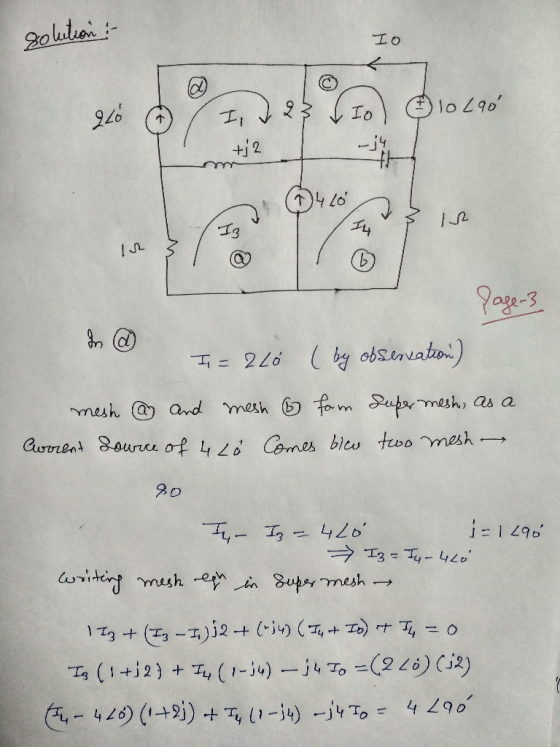
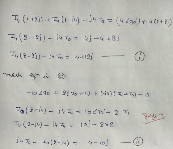
a) Use MultiSim to find Vo in the circuit below. Paste your Multisim circuit showing the value of Vo in the space below...
 a) Use MultiSim to find Vo in the circuit below. Paste your
Multisim circuit showing the value of Vo in the space below.
b) Use mesh analysis to solve the same problem by hand. Show
your work in the space below. Compare the Multisim answer to that
obtained by hand. Are they the same?
5 A 2Ω 20 V 412 40 V (+ V: 27.1 V V(PP): 2.07 pv V(rms): 0Vv V(dc): 27.1V V(freq): 5A R2 R3 PR1 R1 2Ω...
a) Use MultiSim to find Vo in the circuit below. Paste your
Multisim circuit showing the value of Vo in the space below.
b) Use mesh analysis to solve the same problem by hand. Show
your work in the space below. Compare the Multisim answer to that
obtained by hand. Are they the same?
5 A 2Ω 20 V 412 40 V (+ V: 27.1 V V(PP): 2.07 pv V(rms): 0Vv V(dc): 27.1V V(freq): 5A R2 R3 PR1 R1 2Ω...
 Problem 1. Perform the following for the circuit below using the node voltage method: 10Ω 10Ω 5i a) Calculate ia b) Calculate v c) Calculate Psource,5ia Problem 2. Perform the following for the circuit below using the node voltage method: 10Ω 1 4Ω 2 60V+ 30A V. 3 2Ω 5Ω 3 a) Calculate vi, v2 and vs b) Calculate Psource 30A c) Calculate Psource,Gov node voltage method Problem 3. Perform the following for the circuit below using the 10V 4Ω...
 Use the node-voltage method, find the steady-state expression for vo (t) in the following circuit if v,(t) 20 cos(5000t +60) V and v2 (t)10sin(50001) V 0.8mH 8S2 it40uF
 Question (1): Using node voltage method. Find v. 2Ω , 8Ω 4Ω 20V 40 V -
 Use the node-voltage method to find the steady-state expression
for vo(t) in the circuit in (Figure 1) if
vg1= 19 sin(400t+143.13∘)V,
vg2= 18.03cos(400t+33.69∘)V.
Write the steady-state expression for vo(t) as vo=Vocos(ωt+ϕ),
where −180∘<ϕ≤180∘.
EE 211/EE 212 FA19 Circuits Analysis for Engineers KEE 211/212 HW #10 -- Impedances, Sinusoidal Steady State Analysis Problem 9.57 PSpicelMultisim Use the node-voltage method to find the steady-state expression for (t) in the circuit in (Figure 1) if gl19 sin(400t143.13°) V. g218.03 cos(400t 33.69o) V. Write...
Use the node-voltage method to find the steady-state expression
for vo(t) in the circuit in (Figure 1) if
vg1= 19 sin(400t+143.13∘)V,
vg2= 18.03cos(400t+33.69∘)V.
Write the steady-state expression for vo(t) as vo=Vocos(ωt+ϕ),
where −180∘<ϕ≤180∘.
EE 211/EE 212 FA19 Circuits Analysis for Engineers KEE 211/212 HW #10 -- Impedances, Sinusoidal Steady State Analysis Problem 9.57 PSpicelMultisim Use the node-voltage method to find the steady-state expression for (t) in the circuit in (Figure 1) if gl19 sin(400t143.13°) V. g218.03 cos(400t 33.69o) V. Write...
 1. Use PSpice to find the node voltages for the following circuit. 2% 12 4Ω ΙΩ 4Ω 10 V I A 2. Use PSpice to find the mesh currents for the following circuit. 8Ω 3 A 12 V 40(із 2u
 The source voltage vg in the circuit in figure equals 32 V. Use
the node-voltage method to find the power developed by the 32 V
source.
****NOT A 20V BUT A 32 V SOURCE. DISREGARD WHAT THE PICTURE
SAYS. JUST USE THE PICTURE FOR THE CIRCUIT***
Use the node-voltage method to find the power devel- oped by the 20 V source in the circuit 35 i 2Ω 1Ω 4Ω ぢ> 3.125 v
The source voltage vg in the circuit in figure equals 32 V. Use
the node-voltage method to find the power developed by the 32 V
source.
****NOT A 20V BUT A 32 V SOURCE. DISREGARD WHAT THE PICTURE
SAYS. JUST USE THE PICTURE FOR THE CIRCUIT***
Use the node-voltage method to find the power devel- oped by the 20 V source in the circuit 35 i 2Ω 1Ω 4Ω ぢ> 3.125 v
 Please do parts b-d.
2. Consider the circuit shown below. 0.2i 7 2 4Ω 1Ω 4Ω 0.1 va (a) By hand, use any method (node voltage, mesh currents, etc.) tosolve for the currentix b) Using Spice, solve for ix and compare with your hand calculation. (c) Plot Va vs. Vs, where Vs replaces the 9 V voltage source (and has the same polarity) and varies from -20 to 20 volts. At what value of Vs does the direction of the...
Please do parts b-d.
2. Consider the circuit shown below. 0.2i 7 2 4Ω 1Ω 4Ω 0.1 va (a) By hand, use any method (node voltage, mesh currents, etc.) tosolve for the currentix b) Using Spice, solve for ix and compare with your hand calculation. (c) Plot Va vs. Vs, where Vs replaces the 9 V voltage source (and has the same polarity) and varies from -20 to 20 volts. At what value of Vs does the direction of the...
 Use the node voltage method to find the steady-state expression for io in the circuit seen in (Figure 1) if ig 4 cos 2500t A and v, 16 cos(2500t + 90° ) V Write the steady-state expression for io(t) as to = L cos(wt + φ), where-180° <φ < 180° Figure く 1of1 100 μF 50 uF 12Ω View "31.6 mH 30
 Problem #1: Circuit Analysis and Thevenin Equivalent [20 points] The bridge circuit is connected to a load RL between terminals (a, b) as shown (a) Use node-voltage method to solve for VTH respect to terminal (a, b) (b) Use mesh-current method to solve for isc respect to terminal (a, b) 5Ω 2Ω 2 Ri b al 16 V 4Ω 2Ω
 a) Use MultiSim to find Vo in the circuit below. Paste your
Multisim circuit showing the value of Vo in the space below.
b) Use mesh analysis to solve the same problem by hand. Show
your work in the space below. Compare the Multisim answer to that
obtained by hand. Are they the same?
5 A 2Ω 20 V 412 40 V (+ V: 27.1 V V(PP): 2.07 pv V(rms): 0Vv V(dc): 27.1V V(freq): 5A R2 R3 PR1 R1 2Ω...
a) Use MultiSim to find Vo in the circuit below. Paste your
Multisim circuit showing the value of Vo in the space below.
b) Use mesh analysis to solve the same problem by hand. Show
your work in the space below. Compare the Multisim answer to that
obtained by hand. Are they the same?
5 A 2Ω 20 V 412 40 V (+ V: 27.1 V V(PP): 2.07 pv V(rms): 0Vv V(dc): 27.1V V(freq): 5A R2 R3 PR1 R1 2Ω...
Most questions answered within 3 hours.
-
Accent Software faces the following conditions. All of these
support Accent’s use of a market-penetration pricing...
asked 10 minutes ago -
A mathematically inclined friend emails you the following
instructions: "Meet me in the cafeteria the first...
asked 13 minutes ago -
A monopoly sells in two countries . The demand curves in the two
countries are p1...
asked 1 hour ago -
A .15kg rubber ball is bounced off a wall. Before hitting the
wall, the ball moves...
asked 1 hour ago -
A manufacturing company preparing to build a new plant is
considering three potential locations for it....
asked 1 hour ago -
B. If compound Y has approximately the same values of solubility
in toluene as compound X,...
asked 2 hours ago -
Oscar Inc. has inventory in Japan valued at 39,051,000 Yen one
year ago. One year ago...
asked 2 hours ago -
If Canada suffered from "fundamental disequilibrium," and its
government choose not to devalue its currency, a...
asked 2 hours ago -
4. How many input & output Key Value Pairs are passed into,
and emitted out of...
asked 2 hours ago -
Why would your heart not function well if constructed of
skeletal muscle? What is the particular...
asked 2 hours ago -
Please respond to this essay question in full essay form for
Chemistry 1102 Organic and Biochemistry:...
asked 2 hours ago -
Determine the head loss and velocity of flow in a water supply main
of 15.0 cm...
asked 3 hours ago