
Homework Answers
see pictures:

Add Answer to:
In the figure the resistances are R_1 = 1.0 ohm and R_2 = 2.7 ohm, and...
A battery V = 24.0 volts, a resistor R_1 = 12.0 Ohm and a resistor R_2...
 A battery V = 24.0 volts, a resistor R_1 = 12.0 Ohm and a
resistor R_2 = 4.0 Ohm are wired into a circuit with an ideal
voltmeter connected across R_2. See the figure. What is the reading
of the voltmeter?
A battery V = 24.0 volts, a resistor R_1 = 12.0 Ohm and a resistor R_2 = 4.0 Ohm are wired into a circuit with an ideal voltmeter connected across R_2. See the figure. What is the reading of...
A battery V = 24.0 volts, a resistor R_1 = 12.0 Ohm and a
resistor R_2 = 4.0 Ohm are wired into a circuit with an ideal
voltmeter connected across R_2. See the figure. What is the reading
of the voltmeter?
A battery V = 24.0 volts, a resistor R_1 = 12.0 Ohm and a resistor R_2 = 4.0 Ohm are wired into a circuit with an ideal voltmeter connected across R_2. See the figure. What is the reading of...
In the figure the ideal battery has emf = 32.8 V, and the resistances are R_1...
 In the figure the ideal battery has emf = 32.8 V, and the resistances are R_1 = R_2 = 18 Ohm, R_3 = R_4 = R_5 = 6.6 Ohm, R_6 = 4.9 Ohm, and R_7 = 3.9 Ohm. What are currents (a) i_2, (b) i_4, (c) i_1, (d) i_3, and (e) i_5?.
In the circuit shown below, what is the rate at which energy is dissipated in (a)...
 In the circuit shown below, what is the rate at which energy is dissipated in (a) R_1, (b) R_2, and (c) R_3? What is the power of (d) battery 1 and (e) battery 2? Put epsilon_1 = 3.0 V, epsilon_2 = 1.0 V, R_1 = 5.0 ohm, and R_2 = 2.0 ohm, R_3 = 4.0 ohm, both batteries are ideal.
Consider the circuit shown in the figure below.(Assume R_1 = 11.5 ohm and R_2 = 3.50...
 Consider the circuit shown in the figure below.(Assume R_1 = 11.5 ohm and R_2 = 3.50 ohm.) v find the potential difference between points a and b. Find the current in the 20.0-ohm resistor. A
In the figure the resistances are R1 = 0.94 Ω and R2-1.9 Ω, and the ideal...
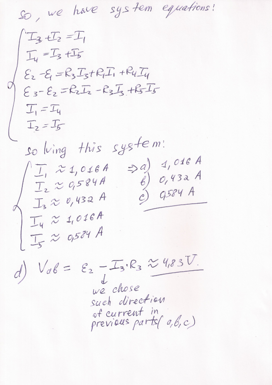
 In the figure the resistances are R1 = 0.94 Ω and R2-1.9 Ω, and the ideal batteries have emfs ε,-2.4 V, and ε2E3-5.9 V. what are the (a) size and (b) direction (up or down) of the current in battery 1, the (c) size and (d) direction of the current in battery 2, and the (e) size and (f) direction of the current in battery 3? (g) What is the potential difference Va - Vb R2 (a) Number Units (c)...
In the figure the resistances are R1 = 1.3 omega and R2 = 2.6 omega, and...
 In the figure the resistances are R1 = 1.3 omega and R2 = 2.6 omega, and the ideal batteries have emfs epsilon 1 = 2.4 V, and epsilon 2 = epsilon 3 = 4.5 V. What are the size and direction (up or down) of the current in battery 1, the size and direction of the current in battery 2, and the size and direction of the current in battery 3? What is the potential difference Va - Vb? Number...
In the figure below. E = 9.00 V, R_1 = 100 Ohm, R_2 = 500 Ohm,...
 In the figure below. E = 9.00 V, R_1 = 100 Ohm, R_2 = 500 Ohm, and R_3 = 700 Ohm. (a) What is the equivalent resistance of the three resistors? (b) What is the electric potential across resistance 1? (c) What is the current through resistance 3?
Question 3 In the figure the resistances are R1 1.3 Q and R2 2.6 Q, and...
 Question 3 In the figure the resistances are R1 1.3 Q and R2 2.6 Q, and the ideal batteries have emfs E12.0 V, and 283 4.8 V. What are the (a) size and (b) direction (up or down) of the current in battery 1, the (c) size and (d) direction of the current in battery 2, and the (e) size and (f) direction of the current in battery 3? (g) What is the potential difference Va-Vb? Ri Ri t, Ry...
In the figure below, the ideal battery has emf E = 30.0 V, R_1 = R_2...
 In the figure below, the ideal battery has emf E = 30.0 V, R_1 = R_2 = 12 Ohm, R_3 = R_4 = R_5 = 5.6 Ohm, R_6 = 2.0 Ohm, and R_7 = 1.5 Ohm. (a) What is current i_2? (b) What is current i_4? (c) What is current i_1? (d) What is current i_3? (e) what is current is i_5?
In Figures 28.4 and 28.6, let R_1 = 14.0 Ohm, let R_2 = 22.0 Ohm, and...
 In Figures 28.4 and 28.6, let R_1 = 14.0 Ohm, let R_2 = 22.0 Ohm, and let the battery have a terminal voltage of 38.0 V. (a) In the parallel circuit shown in Figure 28.6, to which resistor is more power delivered? R_2 R_1 (b) Calculate the sum of the power (^2R) delivered to each resistor. Calculate the power supplied by the battery (I Delta V). W (c) In the series circuit, which resistor uses more power? R_2 R_1 (d)...
 A battery V = 24.0 volts, a resistor R_1 = 12.0 Ohm and a
resistor R_2 = 4.0 Ohm are wired into a circuit with an ideal
voltmeter connected across R_2. See the figure. What is the reading
of the voltmeter?
A battery V = 24.0 volts, a resistor R_1 = 12.0 Ohm and a resistor R_2 = 4.0 Ohm are wired into a circuit with an ideal voltmeter connected across R_2. See the figure. What is the reading of...
A battery V = 24.0 volts, a resistor R_1 = 12.0 Ohm and a
resistor R_2 = 4.0 Ohm are wired into a circuit with an ideal
voltmeter connected across R_2. See the figure. What is the reading
of the voltmeter?
A battery V = 24.0 volts, a resistor R_1 = 12.0 Ohm and a resistor R_2 = 4.0 Ohm are wired into a circuit with an ideal voltmeter connected across R_2. See the figure. What is the reading of...
 In the figure the ideal battery has emf = 32.8 V, and the resistances are R_1 = R_2 = 18 Ohm, R_3 = R_4 = R_5 = 6.6 Ohm, R_6 = 4.9 Ohm, and R_7 = 3.9 Ohm. What are currents (a) i_2, (b) i_4, (c) i_1, (d) i_3, and (e) i_5?.
 In the circuit shown below, what is the rate at which energy is dissipated in (a) R_1, (b) R_2, and (c) R_3? What is the power of (d) battery 1 and (e) battery 2? Put epsilon_1 = 3.0 V, epsilon_2 = 1.0 V, R_1 = 5.0 ohm, and R_2 = 2.0 ohm, R_3 = 4.0 ohm, both batteries are ideal.
 Consider the circuit shown in the figure below.(Assume R_1 = 11.5 ohm and R_2 = 3.50 ohm.) v find the potential difference between points a and b. Find the current in the 20.0-ohm resistor. A
 In the figure the resistances are R1 = 0.94 Ω and R2-1.9 Ω, and the ideal batteries have emfs ε,-2.4 V, and ε2E3-5.9 V. what are the (a) size and (b) direction (up or down) of the current in battery 1, the (c) size and (d) direction of the current in battery 2, and the (e) size and (f) direction of the current in battery 3? (g) What is the potential difference Va - Vb R2 (a) Number Units (c)...
 In the figure the resistances are R1 = 1.3 omega and R2 = 2.6 omega, and the ideal batteries have emfs epsilon 1 = 2.4 V, and epsilon 2 = epsilon 3 = 4.5 V. What are the size and direction (up or down) of the current in battery 1, the size and direction of the current in battery 2, and the size and direction of the current in battery 3? What is the potential difference Va - Vb? Number...
 In the figure below. E = 9.00 V, R_1 = 100 Ohm, R_2 = 500 Ohm, and R_3 = 700 Ohm. (a) What is the equivalent resistance of the three resistors? (b) What is the electric potential across resistance 1? (c) What is the current through resistance 3?
 Question 3 In the figure the resistances are R1 1.3 Q and R2 2.6 Q, and the ideal batteries have emfs E12.0 V, and 283 4.8 V. What are the (a) size and (b) direction (up or down) of the current in battery 1, the (c) size and (d) direction of the current in battery 2, and the (e) size and (f) direction of the current in battery 3? (g) What is the potential difference Va-Vb? Ri Ri t, Ry...
 In the figure below, the ideal battery has emf E = 30.0 V, R_1 = R_2 = 12 Ohm, R_3 = R_4 = R_5 = 5.6 Ohm, R_6 = 2.0 Ohm, and R_7 = 1.5 Ohm. (a) What is current i_2? (b) What is current i_4? (c) What is current i_1? (d) What is current i_3? (e) what is current is i_5?
 In Figures 28.4 and 28.6, let R_1 = 14.0 Ohm, let R_2 = 22.0 Ohm, and let the battery have a terminal voltage of 38.0 V. (a) In the parallel circuit shown in Figure 28.6, to which resistor is more power delivered? R_2 R_1 (b) Calculate the sum of the power (^2R) delivered to each resistor. Calculate the power supplied by the battery (I Delta V). W (c) In the series circuit, which resistor uses more power? R_2 R_1 (d)...
Most questions answered within 3 hours.
-
A 0.035 mol sample of a weak acid, HA, is dissolved in 437 mL of
water...
asked 3 seconds from now -
a sample of Ar gas has a volume of 6.30 L with an unknown
pressure. the...
asked 38 seconds ago -
The
serum cholesterol levels of a population of kids follow a normal
distribution with mean 155...
asked 20 minutes ago -
han discusses the racist practice of badlands, a bar
in the Castro
district of San Francisco,...
asked 32 minutes ago -
A sample of final exam scores is normally distributed with a
mean equal to 25 and...
asked 35 minutes ago -
An investor shorts 100 shares of a stock when the share price is
$50 and closes...
asked 39 minutes ago -
LLOP corporation just paid 4$ dividend per share, you expect the
dividend to grow 8% for...
asked 49 minutes ago -
if we subtract 1000 from 0001 is there overflow? (binary)
asked 57 minutes ago -
Hello, I need help with the function below, The language I am
using is Ocaml
open...
asked 58 minutes ago -
Explain how the presence of glucose represses the gal structural
genes?
asked 1 hour ago -
For the reaction CaI2+2AgNO3⟶2AgI+Ca(NO3)2 how many grams of
silver iodide, AgI, are produced from 56.5 g...
asked 1 hour ago -
Write an equation for hydrolysis via acid catalysis.
Using ethyl acetate, ethyl benzoate, ethyl formate or...
asked 1 hour ago