

Homework Answers


Add Answer to:
Question 2: The shaft ABC shown in the figure is driven by a motor that delivers...
The motor shown in the figure supplies 14.0 kW at 1880 rpm at A. Shafts (1)...
 The motor shown in the figure supplies 14.0 kW at 1880 rpm at
A. Shafts (1) and (2) are each solid 26 mm diameter
shafts. Shaft (1) is made of an aluminum alloy [?G=26??GPa], and
shaft (2) is made of bronze [?G=45??GPa]. The shaft lengths are
L1=3.1m and L2=2.7m, respectively. Gear B has 55 teeth,
and gear C has 99 teeth. The bearings shown permit free
rotation of the shafts. Determine:
(a) the maximum shear stress produced in shafts
(1)...
The motor shown in the figure supplies 14.0 kW at 1880 rpm at
A. Shafts (1) and (2) are each solid 26 mm diameter
shafts. Shaft (1) is made of an aluminum alloy [?G=26??GPa], and
shaft (2) is made of bronze [?G=45??GPa]. The shaft lengths are
L1=3.1m and L2=2.7m, respectively. Gear B has 55 teeth,
and gear C has 99 teeth. The bearings shown permit free
rotation of the shafts. Determine:
(a) the maximum shear stress produced in shafts
(1)...
Question 1 The motor shown in Fig. 1 supplies power to Gear C through solid steel...
 Question 1 The motor shown in Fig. 1 supplies power to Gear C through solid steel motor shaft GF (having a diamet of 200 mm) and Gear F. The torque delivered to Gear C is 200 kNm. Gears A, B, D and E supply powers to er three machines. The torques delivered by gear A, gear B and gear E to the machines are 60 kNm, 30 kNm and 40 kNm, respectively. Shaft ABCDE is also made of steel (G...
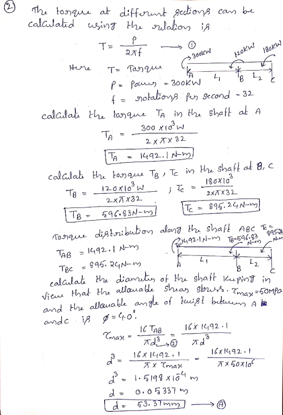
Problem 2: A solid steel shaft ABC of 50 mm diameter is driven at A by...
 Problem 2: A solid steel shaft ABC of 50 mm diameter is driven at A by a motor that transmits 50 kW to the shaft at 40 rpm. The gears at B and C drive require 35 and 15 kW, respectively. Calculate the maximum shear stress in the shaft and the angle of twist between A and C. G 80 GPa 10 marks Motor 50 mm
The composite shaft shown consists of a 0.2-in-thick brass jacket (G = 5.6 x 10 psi)...
 The composite shaft shown consists of a 0.2-in-thick brass jacket (G = 5.6 x 10 psi) bonded to a 1.2-in.-diameter steel core (Gsteel = 11.2 x 10 psi). Knowing that the shaft is subjected to 5 kip-in. torques, determine: 1. The torques in steel and brass. 2. The maximum shearing stress in the brass jacket. 3. The maximum shearing stress in the steel core. (Note: the angle of twist in steel equals to the angle of twist in brass) 6...
Question 15 The composite shaft shown consists of a 0.2-in-thick brass jacket (G = 5.6 x...
 Question 15 The composite shaft shown consists of a 0.2-in-thick brass jacket (G = 5.6 x 10⁶ psi) bonded to a 1.2-in.-diameter steel core (Gsteel = 11.2 x 10⁶ psi). Knowing that the shaft is subjected to 5 kip-in. torques, determine: 1. The torques in steel and brass. 2. The maximum shearing stress in the brass jacket. 3. The maximum shearing stress in the steel core. (Note: the angle of twist in steel equals to the angle of twist in...
Your answer is partially correct. Try again. A motor supplies 178 ho at 540 rpm to...
 Your answer is partially correct. Try again. A motor supplies 178 ho at 540 rpm to flange A of the shaft. Gear B transfers 63hp of power to operating machinery in the factory, and the remaining pow in the factory, and the remaining power in the shaft is transferred by i te s stonuee th gear D. Shafts (1) and (2) are solid aluminum [G 4600 ksi] shafts that have the same diameter and an allowable shear stress of 5.9...
P6.18 The gear train system shown in Figure P6.18/19 includes shafts (1) and (2), which are...
 P6.18 The gear train system shown in Figure P6.18/19 includes shafts (1) and (2), which are solid 15 mm diameter steel shafts. The allowable shear stress of each shaft is 85 MPa. The diameter of gear B is Ds 200 mm, and the diameter of gear C is Dc 150 mm. The bearings shown allow the shafts to rotate freely. Determine the maximum torque TD that can be applied to the system without exceeding the allowable shear stress in either...
Part 1. For the solid steel shaft shown (G = 1 1-2 x 10⁶ psi) determine...
 Part 1. For the solid steel shaft shown (G = 1 1-2 x 10⁶ psi) determine the angle of twist at A. Part 2. Determine the angle of twist at A assuming the steel shaft is hollow with a 1.2 inch outer diameter and 0.8 inch inner diameter 6 ft 1.2 inA 2 kip in
The gears attached to the fixed-end steel shaft are subjected to the torques shown in the figure. If the shear modulus of elasticity is 150 GPa a determine the following: nd the shaft has a d...
 The gears attached to the fixed-end steel shaft are subjected to the torques shown in the figure. If the shear modulus of elasticity is 150 GPa a determine the following: nd the shaft has a diameter of 14 mm, a. Sketch the torque diagram along the steel shaft. b. Determine the maximum shear stress at Tmax and specify location. c. Sketch the shear stress distribution along the radial line at location specified in (b). d. Determine the displacement of the...
In the mechanical system represented in Figure 2(a), a motor supplies a torque of 45 kN-m,...
 In the mechanical system represented in Figure 2(a), a motor supplies a torque of 45 kN-m, and powers two machines through gears D and E. The torque delivered to gear E is 8 kN-m The two shafts are made of steel, with E200 GPa, G 80 GPa and yield strength of 300 MPa The shaft AB has an outer diameter of 150 mm and an inner diameter of 80 mm; the shaft DCE has an outer diameter of 80 mm...
 The motor shown in the figure supplies 14.0 kW at 1880 rpm at
A. Shafts (1) and (2) are each solid 26 mm diameter
shafts. Shaft (1) is made of an aluminum alloy [?G=26??GPa], and
shaft (2) is made of bronze [?G=45??GPa]. The shaft lengths are
L1=3.1m and L2=2.7m, respectively. Gear B has 55 teeth,
and gear C has 99 teeth. The bearings shown permit free
rotation of the shafts. Determine:
(a) the maximum shear stress produced in shafts
(1)...
The motor shown in the figure supplies 14.0 kW at 1880 rpm at
A. Shafts (1) and (2) are each solid 26 mm diameter
shafts. Shaft (1) is made of an aluminum alloy [?G=26??GPa], and
shaft (2) is made of bronze [?G=45??GPa]. The shaft lengths are
L1=3.1m and L2=2.7m, respectively. Gear B has 55 teeth,
and gear C has 99 teeth. The bearings shown permit free
rotation of the shafts. Determine:
(a) the maximum shear stress produced in shafts
(1)...
 Question 1 The motor shown in Fig. 1 supplies power to Gear C through solid steel motor shaft GF (having a diamet of 200 mm) and Gear F. The torque delivered to Gear C is 200 kNm. Gears A, B, D and E supply powers to er three machines. The torques delivered by gear A, gear B and gear E to the machines are 60 kNm, 30 kNm and 40 kNm, respectively. Shaft ABCDE is also made of steel (G...
 Problem 2: A solid steel shaft ABC of 50 mm diameter is driven at A by a motor that transmits 50 kW to the shaft at 40 rpm. The gears at B and C drive require 35 and 15 kW, respectively. Calculate the maximum shear stress in the shaft and the angle of twist between A and C. G 80 GPa 10 marks Motor 50 mm
 The composite shaft shown consists of a 0.2-in-thick brass jacket (G = 5.6 x 10 psi) bonded to a 1.2-in.-diameter steel core (Gsteel = 11.2 x 10 psi). Knowing that the shaft is subjected to 5 kip-in. torques, determine: 1. The torques in steel and brass. 2. The maximum shearing stress in the brass jacket. 3. The maximum shearing stress in the steel core. (Note: the angle of twist in steel equals to the angle of twist in brass) 6...
 Question 15 The composite shaft shown consists of a 0.2-in-thick brass jacket (G = 5.6 x 10⁶ psi) bonded to a 1.2-in.-diameter steel core (Gsteel = 11.2 x 10⁶ psi). Knowing that the shaft is subjected to 5 kip-in. torques, determine: 1. The torques in steel and brass. 2. The maximum shearing stress in the brass jacket. 3. The maximum shearing stress in the steel core. (Note: the angle of twist in steel equals to the angle of twist in...
 Your answer is partially correct. Try again. A motor supplies 178 ho at 540 rpm to flange A of the shaft. Gear B transfers 63hp of power to operating machinery in the factory, and the remaining pow in the factory, and the remaining power in the shaft is transferred by i te s stonuee th gear D. Shafts (1) and (2) are solid aluminum [G 4600 ksi] shafts that have the same diameter and an allowable shear stress of 5.9...
 P6.18 The gear train system shown in Figure P6.18/19 includes shafts (1) and (2), which are solid 15 mm diameter steel shafts. The allowable shear stress of each shaft is 85 MPa. The diameter of gear B is Ds 200 mm, and the diameter of gear C is Dc 150 mm. The bearings shown allow the shafts to rotate freely. Determine the maximum torque TD that can be applied to the system without exceeding the allowable shear stress in either...
 Part 1. For the solid steel shaft shown (G = 1 1-2 x 10⁶ psi) determine the angle of twist at A. Part 2. Determine the angle of twist at A assuming the steel shaft is hollow with a 1.2 inch outer diameter and 0.8 inch inner diameter 6 ft 1.2 inA 2 kip in
 The gears attached to the fixed-end steel shaft are subjected to the torques shown in the figure. If the shear modulus of elasticity is 150 GPa a determine the following: nd the shaft has a diameter of 14 mm, a. Sketch the torque diagram along the steel shaft. b. Determine the maximum shear stress at Tmax and specify location. c. Sketch the shear stress distribution along the radial line at location specified in (b). d. Determine the displacement of the...
 In the mechanical system represented in Figure 2(a), a motor supplies a torque of 45 kN-m, and powers two machines through gears D and E. The torque delivered to gear E is 8 kN-m The two shafts are made of steel, with E200 GPa, G 80 GPa and yield strength of 300 MPa The shaft AB has an outer diameter of 150 mm and an inner diameter of 80 mm; the shaft DCE has an outer diameter of 80 mm...
Most questions answered within 3 hours.
-
A student takes a multiple-choice test that has 10 questions.
Each question has two choices. The...
asked 7 minutes ago -
Willie Keeler has a lifetime batting average of 0.341. Assume
that Willie Keeler came to bat...
asked 9 minutes ago -
Which of the following has the highest boiling point?
A) 0.5m NaCl
B) 0.5m C6H12O6
C)...
asked 28 minutes ago -
12. A firm is producing at an output level where
AR = MC > AC >...
asked 25 minutes ago -
Radovilsky Manufacturing Company, in Hayward, California,
makes flashing lights for toys. The company operates its production...
asked 27 minutes ago -
As an athlete exercises, sweat is produced and evaporated to
jelp maintain a proper body temperature....
asked 27 minutes ago -
Which of these macromolecules is most prevalent (by mass) in the
environment? What particular challenge does...
asked 28 minutes ago -
Consider two stocks. Stock A has a standard deviation of 46% and
stock B has a...
asked 32 minutes ago -
Give a unary language (using only input alphabet ∑={1} )that is
not Turing- recognizable and prove...
asked 43 minutes ago -
1. Write the balanced net reaction for a Ti (s) | TiCl2 (aq) ||
InCl3 (aq)...
asked 40 minutes ago -
3) Answer the following questions:please respond in one
paragraph
In your opinion, what are the crucial...
asked 47 minutes ago -
Assume that the readings at freezing on a batch of thermometers
are normally distributed with a...
asked 52 minutes ago