
Homework Answers


Add Answer to:
3. Without writing shear and moment equations, draw shear and moment diagrams and indicate the values...
Draw the Shear and Moment Diagrams for the loaded beam. Indicate where the maximum shear (V)...
 Draw the Shear and Moment Diagrams for the loaded beam. Indicate where the maximum shear (V) and moment (M) values are and where the shear is zero. 3 kN/m
Draw the shear and moment diagrams, and provide shear/moment equations for the beam with following parameters:...
 Draw the shear and moment diagrams, and provide shear/moment
equations for the beam with
following parameters: P1 = 30 kN; P2 = 50 kN; a = 1 m; b = 3 m; c =
2 m
Draw the shear and moment diagrams, and provide shear/moment
equations for the beam with
following parameters: P1 = 30 kN; P2 = 50 kN; a = 1 m; b = 3 m; c =
2 m
4. For the beam and loading shown, draw the shear force and bending moment diagrams and...
 4. For the beam and loading shown, draw the shear force and bending moment diagrams and determine the maximum bending and shear force and their locations. 20 KN 40 KN B D 250 mm |--2.5 m- 3m-4-2 m 80 mm 5. For the beam and loading shown, draw the shear force and bending moment diagrams and determine the maximum bending and shear force and their locations. 50 KN
Draw shear force and bending moment diagrams for the following, giving all principal values. 50 KN...
 Draw shear force and bending moment diagrams for the
following, giving all principal values.
50 KN 40 KN 20 AN 30 AN 50 kNm 2m 2m 20 N 20KN kNm 4 m 10 KN 2 m 3 m
Draw shear force and bending moment diagrams for the
following, giving all principal values.
50 KN 40 KN 20 AN 30 AN 50 kNm 2m 2m 20 N 20KN kNm 4 m 10 KN 2 m 3 m
Calculate.... 1. Calculate the support reactions and draw the axial force, shear force and bending moment...
 Calculate....
1. Calculate the support reactions and draw the axial force, shear force and bending moment diagrams for the beams and frame shown in Fig. 1, labelling all important values (such as, but not necessarily limited to, locations of points of inflection and values of shears and moments at supports, intersections and discontinuities). For the portal frame in li) assume there are points of inflection in the columns located 2.4m up from the ground and one in the beam midway...
Calculate....
1. Calculate the support reactions and draw the axial force, shear force and bending moment diagrams for the beams and frame shown in Fig. 1, labelling all important values (such as, but not necessarily limited to, locations of points of inflection and values of shears and moments at supports, intersections and discontinuities). For the portal frame in li) assume there are points of inflection in the columns located 2.4m up from the ground and one in the beam midway...
for the beam shown, draw the shear and moment diagrams. clearly indicate positions where shear us...
 for the beam shown, draw the shear and moment diagrams.
clearly indicate positions where shear us equal to zero and whether
each segment is constant, linear, quadratic, or cubic.
85 kN 24 kN/m Hinge A B ob D С 8 m 8 m 3 m
for the beam shown, draw the shear and moment diagrams.
clearly indicate positions where shear us equal to zero and whether
each segment is constant, linear, quadratic, or cubic.
85 kN 24 kN/m Hinge A B ob D С 8 m 8 m 3 m
Question 1: (20 Points) For the beam and loading shown: a- Draw shear and moment diagrams. b- Write equations of shear and moment for all segments of the beam from 20 kN 0 kN 8 kN/m x =-4 to x = 8, U...
 Question 1: (20 Points) For the beam and loading shown: a- Draw shear and moment diagrams. b- Write equations of shear and moment for all segments of the beam from 20 kN 0 kN 8 kN/m x =-4 to x = 8, Use x-y axes as shown. Do not change x-y coordinates. Answers: M56 kN-mx4.09 kN-m
Question 1: (20 Points) For the beam and loading shown: a- Draw shear and moment diagrams. b- Write equations of shear and moment for...
Question 1: (20 Points) For the beam and loading shown: a- Draw shear and moment diagrams. b- Write equations of shear and moment for all segments of the beam from 20 kN 0 kN 8 kN/m x =-4 to x = 8, Use x-y axes as shown. Do not change x-y coordinates. Answers: M56 kN-mx4.09 kN-m
Question 1: (20 Points) For the beam and loading shown: a- Draw shear and moment diagrams. b- Write equations of shear and moment for...
draw the shear and bending moment diagrams. determine the maxium absolute values of the sheer bending...
 draw the shear and bending moment diagrams. determine the maxium absolute values of the sheer bending moment. 20 kN/m С M=12 kN.m A B -2 m 2 m
Draw the shear and moment diagrams for the loaded beam. After you have the diagrams, answer...
 Draw the shear and moment
diagrams for the loaded beam. After you have the diagrams, answer
the questions in order to gain confidence in your plots.
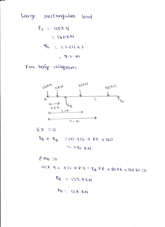
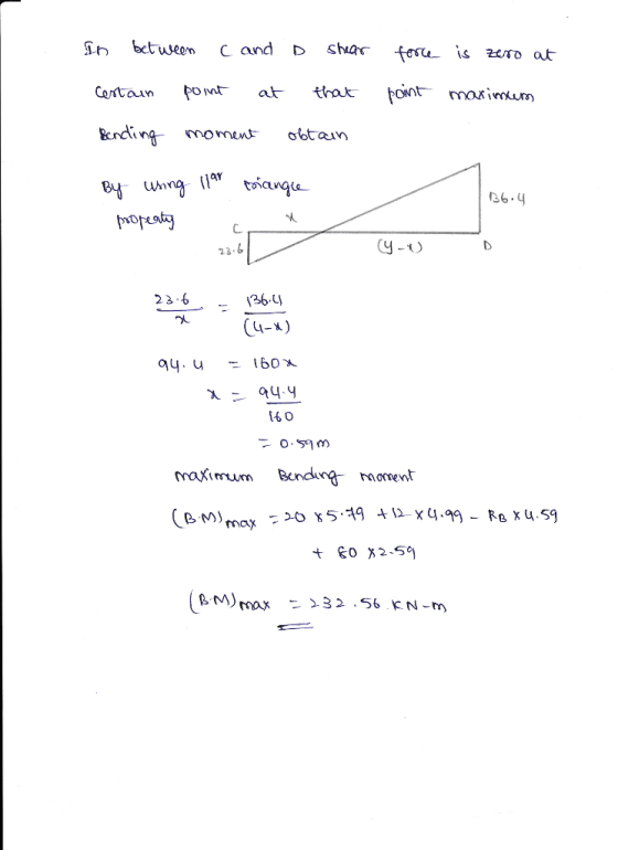
Draw the shear and moment diagrams for the loaded beam. After you have the diagrams, answer the questions in order to gain confidence in your plots. 2 kN 11 kN 5 kNm +3m +4m + 6m — +3m 8 KN Questions: When x = 2.1 m, V = KN.m When x = 5.7 m,...
Draw the shear and moment
diagrams for the loaded beam. After you have the diagrams, answer
the questions in order to gain confidence in your plots.
Draw the shear and moment diagrams for the loaded beam. After you have the diagrams, answer the questions in order to gain confidence in your plots. 2 kN 11 kN 5 kNm +3m +4m + 6m — +3m 8 KN Questions: When x = 2.1 m, V = KN.m When x = 5.7 m,...
For the beam shown in Fig. 9.3, draw the shear force and bending moment diagrams. Use...
 For the beam shown in Fig. 9.3, draw the shear force and bending moment diagrams. Use the area method that relies on the relationships between loading and shear force and between shear force and bending moment. Indicate the slope of the shear force diagram at locations A, B, C, and D using the load information in Fig. 9.3. Indicate the slope of the bending moment diagram at the same four locations using information from the shear force diagram. | 6...
 Draw the Shear and Moment Diagrams for the loaded beam. Indicate where the maximum shear (V) and moment (M) values are and where the shear is zero. 3 kN/m
 Draw the shear and moment diagrams, and provide shear/moment
equations for the beam with
following parameters: P1 = 30 kN; P2 = 50 kN; a = 1 m; b = 3 m; c =
2 m
Draw the shear and moment diagrams, and provide shear/moment
equations for the beam with
following parameters: P1 = 30 kN; P2 = 50 kN; a = 1 m; b = 3 m; c =
2 m
 4. For the beam and loading shown, draw the shear force and bending moment diagrams and determine the maximum bending and shear force and their locations. 20 KN 40 KN B D 250 mm |--2.5 m- 3m-4-2 m 80 mm 5. For the beam and loading shown, draw the shear force and bending moment diagrams and determine the maximum bending and shear force and their locations. 50 KN
 Draw shear force and bending moment diagrams for the
following, giving all principal values.
50 KN 40 KN 20 AN 30 AN 50 kNm 2m 2m 20 N 20KN kNm 4 m 10 KN 2 m 3 m
Draw shear force and bending moment diagrams for the
following, giving all principal values.
50 KN 40 KN 20 AN 30 AN 50 kNm 2m 2m 20 N 20KN kNm 4 m 10 KN 2 m 3 m
 Calculate....
1. Calculate the support reactions and draw the axial force, shear force and bending moment diagrams for the beams and frame shown in Fig. 1, labelling all important values (such as, but not necessarily limited to, locations of points of inflection and values of shears and moments at supports, intersections and discontinuities). For the portal frame in li) assume there are points of inflection in the columns located 2.4m up from the ground and one in the beam midway...
Calculate....
1. Calculate the support reactions and draw the axial force, shear force and bending moment diagrams for the beams and frame shown in Fig. 1, labelling all important values (such as, but not necessarily limited to, locations of points of inflection and values of shears and moments at supports, intersections and discontinuities). For the portal frame in li) assume there are points of inflection in the columns located 2.4m up from the ground and one in the beam midway...
 for the beam shown, draw the shear and moment diagrams.
clearly indicate positions where shear us equal to zero and whether
each segment is constant, linear, quadratic, or cubic.
85 kN 24 kN/m Hinge A B ob D С 8 m 8 m 3 m
for the beam shown, draw the shear and moment diagrams.
clearly indicate positions where shear us equal to zero and whether
each segment is constant, linear, quadratic, or cubic.
85 kN 24 kN/m Hinge A B ob D С 8 m 8 m 3 m
 Question 1: (20 Points) For the beam and loading shown: a- Draw shear and moment diagrams. b- Write equations of shear and moment for all segments of the beam from 20 kN 0 kN 8 kN/m x =-4 to x = 8, Use x-y axes as shown. Do not change x-y coordinates. Answers: M56 kN-mx4.09 kN-m
Question 1: (20 Points) For the beam and loading shown: a- Draw shear and moment diagrams. b- Write equations of shear and moment for...
Question 1: (20 Points) For the beam and loading shown: a- Draw shear and moment diagrams. b- Write equations of shear and moment for all segments of the beam from 20 kN 0 kN 8 kN/m x =-4 to x = 8, Use x-y axes as shown. Do not change x-y coordinates. Answers: M56 kN-mx4.09 kN-m
Question 1: (20 Points) For the beam and loading shown: a- Draw shear and moment diagrams. b- Write equations of shear and moment for...
 draw the shear and bending moment diagrams. determine the maxium absolute values of the sheer bending moment. 20 kN/m С M=12 kN.m A B -2 m 2 m
 Draw the shear and moment
diagrams for the loaded beam. After you have the diagrams, answer
the questions in order to gain confidence in your plots.
Draw the shear and moment diagrams for the loaded beam. After you have the diagrams, answer the questions in order to gain confidence in your plots. 2 kN 11 kN 5 kNm +3m +4m + 6m — +3m 8 KN Questions: When x = 2.1 m, V = KN.m When x = 5.7 m,...
Draw the shear and moment
diagrams for the loaded beam. After you have the diagrams, answer
the questions in order to gain confidence in your plots.
Draw the shear and moment diagrams for the loaded beam. After you have the diagrams, answer the questions in order to gain confidence in your plots. 2 kN 11 kN 5 kNm +3m +4m + 6m — +3m 8 KN Questions: When x = 2.1 m, V = KN.m When x = 5.7 m,...
 For the beam shown in Fig. 9.3, draw the shear force and bending moment diagrams. Use the area method that relies on the relationships between loading and shear force and between shear force and bending moment. Indicate the slope of the shear force diagram at locations A, B, C, and D using the load information in Fig. 9.3. Indicate the slope of the bending moment diagram at the same four locations using information from the shear force diagram. | 6...
Most questions answered within 3 hours.
-
Based on the range, which of the following sets of scores has
the greatest variability? 3,...
asked 37 minutes ago -
Ripples in a pond travel at a velocity of 3 m/s with one peak
passing a...
asked 27 minutes ago -
A man stands on the roof of a building of height 13.0 mm and
throws a...
asked 33 minutes ago -
The extent to which assets are financed by borrowed funds and
other liabilities is indicated by:...
asked 1 hour ago -
Explain in detail
Germany is the fifth largest economy
explain what goods and services Germany specializes...
asked 1 hour ago -
The density of platinum is 21.45 g/mL. If a cube of platinum
with a mass of...
asked 1 hour ago -
Accounts Receivable
Sales
A/R Posting
Extended Sales Invoice
Packing Slip
Compare invoice to packing slip 2...
asked 1 hour ago -
Michaella, age 23, is a full-time law student and is claimed by
her parents as a...
asked 1 hour ago -
Why are polymers not typically casted into products?
asked 2 hours ago -
When rolling a die 129 times, what is the probability of rolling
a 6 no more...
asked 2 hours ago -
4. A call option currently sells for $7.75. It has a strike
price of $85 and...
asked 2 hours ago -
1.
You need to prepare 10.0 liters of an acid aqueous solution with a
pH of...
asked 2 hours ago