
Homework Answers


Add Answer to:
Problem 2: For the system shown in Figure, 01 02 0 when all springs are undefelcted...
Q2 A rotational mechanical system is shown in Figure 2.1. T(t) is the external torque and...
 Q2 A rotational mechanical system is shown in Figure 2.1. T(t) is the external torque and is the input to the system. 01(t) is the angular displacement of inertia Ji and O2(t) is the angular displacement of inertia J2. C and C are friction coefficients and K, and K2 are spring constants. (a) Draw the free-body diagrams for J; and Jz. (7 marks) (b) Derive the equations of motion for the system shown in Figure 2.1. (8 marks) (c) Using...
Problem 2 Determine the transfer function 01(s)/M(s) for the shaft-gear mechanical system in the figure, where...
 Problem 2 Determine the transfer function 01(s)/M(s) for the shaft-gear mechanical system in the figure, where 1(s) and Ms) are the Laplace transforms of the angle 01(t) and of the moment m(t). Use the time-domain mathematical model of this system. Known are J1, ki, J2, c, k2, Ni and N2. N. 1000 0,m 0 000 N Problem 3 By using the transfer function 1(s)/Ms), determined in Problem 2, calculate and plot 01(t) using the step input command of MATLAB. Known...
Question 3) Consider the mechanical system shown in figure, T(t) is the torque applied to shaft...
 Question 3) Consider the mechanical system shown in figure, T(t) is the torque applied to shaft 1 and z(t) is the rotation of shaft 2. J.Jz and Jz are the inertias of shafts 1,2 and 3 respectively, N,,N,N, and N, are the number of teeths of the gears,, D1, D, and D3 are the coefficient of viscous damping associated with shafts 1, 2 and 3 respectively, K is the spring constant of the torsional spring attached to shaft 3. Write...
The system of differential equations for the currents i1 (t) and i2(t) in the electrical network...
 The system of differential equations for the currents i1 (t) and i2(t) in the electrical network shown in the figure is dt(々 =( R2-212/ R2/L1 Use variation of parameters to solve the syster if R1 = 8 Ω, R2-3 Ω, L1 = 1 h, L2-1 h, E(t) = 150 sin(t) V i1(0) = 0, and i2(0) = 0. (i1 (t),ら(t) = R2 し2
Problem 7: Consider the two-degrees of freedom system shown in the figure below, where each disk...
 Problem 7: Consider the two-degrees of freedom system shown in the figure below, where each disk is pivoted at its mass center. The inputs are the torques τι and T2 applied to the pivot points. At t = 0, θί-B2 = τι-T2-0, and each linear spring is at its free length (undeformed). Find the equivalent inertia (la) and stiffness (K matrix T1 T2 02 J2, r2
(1) Consider the RC circuit shown in Figure 1. For t<0 the switch is open, and...
 (1) Consider the RC circuit shown in Figure 1. For t<0 the switch is open, and the charge stored on the capacitor is 0. At t-0 the switch is closed, and the voltage source begins charging the capacitor. Let R1-R2-220 Ω , C-0.47 μ F , Vs-5 V. (a) Write the differential equation as an expression for the capacitor voltage fort> 0 (i.e. write the differential equation) and calculate the time constant (b) Calculate the steady-state capacitor voltage R2 R1...
Problem 3: The system in Figure 3 consists of a double pendulum where both masses are...
 Problem 3: The system in Figure 3 consists of a double pendulum where both masses are m and both lengths are L 2 Figure 3: System for Problem 3 (a) Derive the differential equations of motion for the system. The angles a(t) and θ2(t) can be arbitrarily large. (b) Linearize the equations by assuming that a (t) and 02(t) are small. Write the linearized differential equations in matrix form (c) Obtain the natural frequencies and modes of vibration. (d) Plot...
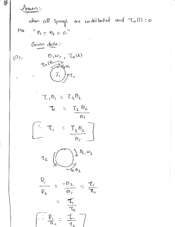
Problem 6: For the system shown below, a torque Ta(t) is applied to the cylinder Λ. iven ,Gear-Ra...
 Problem 6: For the system shown below, a torque Ta(t) is applied to the cylinder Λ. iven ,Gear-Ratio = N = (R) Drmt = (a) Driving a) Find the first order modeling equation in "wi". For parts, b, c and d, use B-N-J2-2:J-0.5 in proper set of units. b) Find and sketch unit step response, yu(t) c) Find and sketch the response when Ta(t)-2 for t > 0; y(0)-A. d) Find and sketch the unit impulse response, h(t). Given.Gear -...
(3) The RL circuit shown in Figure 3 has a switch that is closed att 0....
 (3) The RL circuit shown in Figure 3 has a switch that is closed att 0. Assume that the circuit has reached steady state prior to the switch closing. You are given R1 1 kQ, R2-10 kQ, R3-R4-100 k2, L 10 mH, Vs-5 V. (a) [15 pts] Calculate the steady-state inductor current before the switch is closed (b) [16 pts] Give the differential equation as an expression of the inductor current fort>0 (i.e. write the differential equation) (c) 13 pts]...
Problem 1: The system in Figure 1 comprises two masses connected to one another through a...
 Problem 1: The system in Figure 1 comprises two masses connected to one another through a spring. The block slides without friction on the support and has mass mi. The disk has radius a, mass moment of inertia I, and mass m2. The disk rolls without slipping on the support. The springs are unstretched when x(t) = x2(t) = 0. 2k 3k , m Figure 1: System for Problem 1 (a) Derive the differential equations of motion for the system...
 Q2 A rotational mechanical system is shown in Figure 2.1. T(t) is the external torque and is the input to the system. 01(t) is the angular displacement of inertia Ji and O2(t) is the angular displacement of inertia J2. C and C are friction coefficients and K, and K2 are spring constants. (a) Draw the free-body diagrams for J; and Jz. (7 marks) (b) Derive the equations of motion for the system shown in Figure 2.1. (8 marks) (c) Using...
 Problem 2 Determine the transfer function 01(s)/M(s) for the shaft-gear mechanical system in the figure, where 1(s) and Ms) are the Laplace transforms of the angle 01(t) and of the moment m(t). Use the time-domain mathematical model of this system. Known are J1, ki, J2, c, k2, Ni and N2. N. 1000 0,m 0 000 N Problem 3 By using the transfer function 1(s)/Ms), determined in Problem 2, calculate and plot 01(t) using the step input command of MATLAB. Known...
 Question 3) Consider the mechanical system shown in figure, T(t) is the torque applied to shaft 1 and z(t) is the rotation of shaft 2. J.Jz and Jz are the inertias of shafts 1,2 and 3 respectively, N,,N,N, and N, are the number of teeths of the gears,, D1, D, and D3 are the coefficient of viscous damping associated with shafts 1, 2 and 3 respectively, K is the spring constant of the torsional spring attached to shaft 3. Write...
 The system of differential equations for the currents i1 (t) and i2(t) in the electrical network shown in the figure is dt(々 =( R2-212/ R2/L1 Use variation of parameters to solve the syster if R1 = 8 Ω, R2-3 Ω, L1 = 1 h, L2-1 h, E(t) = 150 sin(t) V i1(0) = 0, and i2(0) = 0. (i1 (t),ら(t) = R2 し2
 Problem 7: Consider the two-degrees of freedom system shown in the figure below, where each disk is pivoted at its mass center. The inputs are the torques τι and T2 applied to the pivot points. At t = 0, θί-B2 = τι-T2-0, and each linear spring is at its free length (undeformed). Find the equivalent inertia (la) and stiffness (K matrix T1 T2 02 J2, r2
 (1) Consider the RC circuit shown in Figure 1. For t<0 the switch is open, and the charge stored on the capacitor is 0. At t-0 the switch is closed, and the voltage source begins charging the capacitor. Let R1-R2-220 Ω , C-0.47 μ F , Vs-5 V. (a) Write the differential equation as an expression for the capacitor voltage fort> 0 (i.e. write the differential equation) and calculate the time constant (b) Calculate the steady-state capacitor voltage R2 R1...
 Problem 3: The system in Figure 3 consists of a double pendulum where both masses are m and both lengths are L 2 Figure 3: System for Problem 3 (a) Derive the differential equations of motion for the system. The angles a(t) and θ2(t) can be arbitrarily large. (b) Linearize the equations by assuming that a (t) and 02(t) are small. Write the linearized differential equations in matrix form (c) Obtain the natural frequencies and modes of vibration. (d) Plot...
 Problem 6: For the system shown below, a torque Ta(t) is applied to the cylinder Λ. iven ,Gear-Ratio = N = (R) Drmt = (a) Driving a) Find the first order modeling equation in "wi". For parts, b, c and d, use B-N-J2-2:J-0.5 in proper set of units. b) Find and sketch unit step response, yu(t) c) Find and sketch the response when Ta(t)-2 for t > 0; y(0)-A. d) Find and sketch the unit impulse response, h(t). Given.Gear -...
 (3) The RL circuit shown in Figure 3 has a switch that is closed att 0. Assume that the circuit has reached steady state prior to the switch closing. You are given R1 1 kQ, R2-10 kQ, R3-R4-100 k2, L 10 mH, Vs-5 V. (a) [15 pts] Calculate the steady-state inductor current before the switch is closed (b) [16 pts] Give the differential equation as an expression of the inductor current fort>0 (i.e. write the differential equation) (c) 13 pts]...
 Problem 1: The system in Figure 1 comprises two masses connected to one another through a spring. The block slides without friction on the support and has mass mi. The disk has radius a, mass moment of inertia I, and mass m2. The disk rolls without slipping on the support. The springs are unstretched when x(t) = x2(t) = 0. 2k 3k , m Figure 1: System for Problem 1 (a) Derive the differential equations of motion for the system...
Most questions answered within 3 hours.
-
Suppose that XX is a random variable with mean 16 and standard
deviation 5 . Also...
asked 1 minute ago -
Calculate the number density of argon gas at a temperature of
24C and a pressure of...
asked 3 hours ago -
Alternative
Classification
How to Estimate
Probabilities from Data? ( For continuous Attributes)
And How to generate...
asked 3 hours ago -
An explosion breaks a 20.0-kg object into three parts. The
object is initially moving at a...
asked 4 hours ago -
Calculate the approximate number of residues of Rubisco, which
is involved in carbon fixation in plants,...
asked 5 hours ago -
Other decisions about scientific claims can have a much broader
impact.ENERGYarrow-10x10.png, environment, health, security - all...
asked 6 hours ago -
I need to write a research paper and work cited about this
topic: The United States...
asked 6 hours ago -
Hello! I was wondering if I could have some help?
If the vapor pressure of carvone...
asked 6 hours ago -
An economist wants to estimate the mean per capita income (in
thousands of dollars) for a...
asked 7 hours ago -
What would be the input/output characteristic of a circuit
obtained by putting two of your 2's-complementers...
asked 7 hours ago -
In Drosophila, the transition from the syncytial blastoderm
stage to the cellular blastoderm stage is a...
asked 7 hours ago -
Project management question:
Name 3 different types of resources (hint: humans are one
type)
asked 7 hours ago