
Homework Answers

Add Answer to:
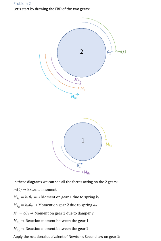
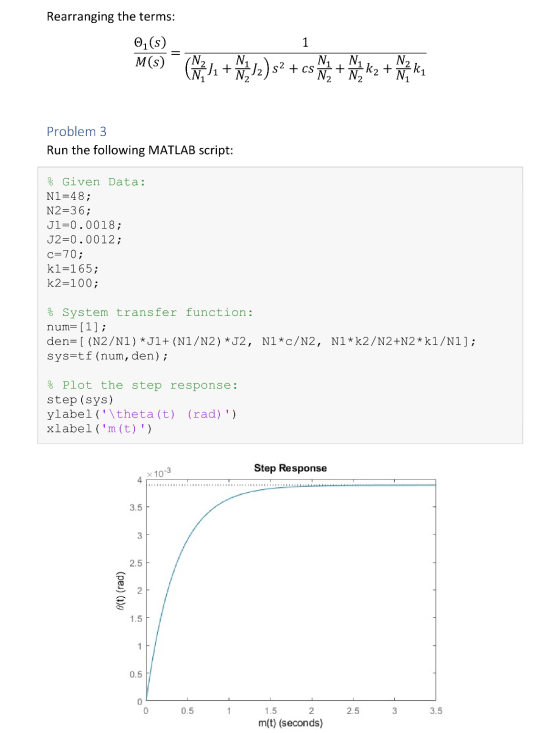
Problem 2 Determine the transfer function 01(s)/M(s) for the shaft-gear mechanical system in the figure, where...
1. Obtain the transfer function G(s)-20 Consider the system of Figure 1. Obtain the transfer func...
 1. Obtain the transfer function G(s)-20 Consider the system of Figure 1. Obtain the transfer function G (s) - of the system in Figure 1 (clearly show the derivation of the model) Question 1.(15) Consider the system of Figure T(s) TO) J1 2 kg-m D1 1 N-m-s/rad J2-1 kg-m2 D2 2 N-m-s/rad K = 64 N-m/rad J-16 kg-m2 D3 32 N-m-s/rad Figure 1
1. Obtain the transfer function G(s)-20 Consider the system of Figure 1. Obtain the transfer function G...
1. Obtain the transfer function G(s)-20 Consider the system of Figure 1. Obtain the transfer function G (s) - of the system in Figure 1 (clearly show the derivation of the model) Question 1.(15) Consider the system of Figure T(s) TO) J1 2 kg-m D1 1 N-m-s/rad J2-1 kg-m2 D2 2 N-m-s/rad K = 64 N-m/rad J-16 kg-m2 D3 32 N-m-s/rad Figure 1
1. Obtain the transfer function G(s)-20 Consider the system of Figure 1. Obtain the transfer function G...
θ2(s)/T(s) for the following rotational mechanical system Problem 4: Find the transfer function G(s) TO) N1...
 θ2(s)/T(s) for the following rotational mechanical system Problem 4: Find the transfer function G(s) TO) N1 = 4 Di 1 N-m-s/rad N2 121 kg-m2 N3-4 D2-2 N-m-s/rad K 64 N-m/rad- N4 16 D3 32 N-m-s/rad -16 kg-m2 000
Question 3) Consider the mechanical system shown in figure, T(t) is the torque applied to shaft...
 Question 3) Consider the mechanical system shown in figure, T(t) is the torque applied to shaft 1 and z(t) is the rotation of shaft 2. J.Jz and Jz are the inertias of shafts 1,2 and 3 respectively, N,,N,N, and N, are the number of teeths of the gears,, D1, D, and D3 are the coefficient of viscous damping associated with shafts 1, 2 and 3 respectively, K is the spring constant of the torsional spring attached to shaft 3. Write...
Problem #5: Transfer Function: Mechanical System 3 2. Variables: Mass terms; mi, m2 Damping term; b1...
 Problem #5: Transfer Function: Mechanical System 3 2. Variables: Mass terms; mi, m2 Damping term; b1 Stiffness terms; ki, k2, k3 Friction term; f Write the equations of motion from applying the law of physics to the system Write Transfer Function, Y(s)/X1(s) a) b)
Problem 51: (25 points) Figure 5 is an example of a feedback control system that is designed to r...
 Problem 51: (25 points) Figure 5 is an example of a feedback control system that is designed to regulate the angular position θ(t) of a motor shaft to a desired value θr(t). The signal e(t) represents the error between the measured shaft angle θ(t) and the desired shaft angle θ (t). The Laplace transforms ofa,(t), θ(t), and e(t) are denoted as ΘR(s), θ(s), and E(s), respectively. The control gains Ki and K2 are chosen by the control engineer to achieve...
i want to get part c,d The figure below is a gear-train mechanical system driven by...
 i want to get part c,d
The figure below is a gear-train mechanical system driven by a prescribed motion in the form of an angular displacement y(t). The motion is caused by an applied torque T(t) generated by a motor. The mass moment of inertias of the motor and the driving gear are J and J, respectively, whereas the mass moment of inertias of the load and the driven gear are J, and J2, respectively. The radii and angular displacements...
i want to get part c,d
The figure below is a gear-train mechanical system driven by a prescribed motion in the form of an angular displacement y(t). The motion is caused by an applied torque T(t) generated by a motor. The mass moment of inertias of the motor and the driving gear are J and J, respectively, whereas the mass moment of inertias of the load and the driven gear are J, and J2, respectively. The radii and angular displacements...
Problem 2: For the system shown in Figure, 01 02 0 when all springs are undefelcted...
 Problem 2: For the system shown in Figure, 01 02 0 when all springs are undefelcted and ta(t) 0. Write the modeling equations for 01 with the following two methods. (25 points) (1) Draw FBD for Ji, and J2, write the differential equations for 01 (15 points). (2) Based on the equivalent parameters reflected from shift of J2 to shaft of Ji, simplify the system and writing the modeling equations for 01 (10 points). R1 t) J, R2 Figure 2
Q2 A rotational mechanical system is shown in Figure 2.1. T(t) is the external torque and...
 Q2 A rotational mechanical system is shown in Figure 2.1. T(t) is the external torque and is the input to the system. 01(t) is the angular displacement of inertia Ji and O2(t) is the angular displacement of inertia J2. C and C are friction coefficients and K, and K2 are spring constants. (a) Draw the free-body diagrams for J; and Jz. (7 marks) (b) Derive the equations of motion for the system shown in Figure 2.1. (8 marks) (c) Using...
a) Develop the transfer function X:(s)/F(s) of the mechanical system shown in Figure 3(a). Give and...
 a) Develop the transfer function X:(s)/F(s) of the mechanical system shown in Figure 3(a). Give and explain one example the real application where you can relate with this system. (5 marks) b) Routh's stability criterion is of limited usefulness in linear control systems analysis mainly because it does not suggest how to stabilize an unstable system. Thus, we should evaluate the stability range of a parameter value. Consider the servo system with tachometer feedback as shown in Figure 3(b). Evaluate...
IL IULIUCI. (Q3) Consider below rotational mechanical system. Find the transfer function between 02(s) and T(s),...
 IL IULIUCI. (Q3) Consider below rotational mechanical system. Find the transfer function between 02(s) and T(s), that is find G(s) = 0; (5) T(s) en(t) T(t) 1) N1=20 W 1 N3=30 02(t) 450 kg.m? N2=100 225 N.m/rad --00004 Ny=90 5 N.m.s/rad 3 N.m.s/rad
 1. Obtain the transfer function G(s)-20 Consider the system of Figure 1. Obtain the transfer function G (s) - of the system in Figure 1 (clearly show the derivation of the model) Question 1.(15) Consider the system of Figure T(s) TO) J1 2 kg-m D1 1 N-m-s/rad J2-1 kg-m2 D2 2 N-m-s/rad K = 64 N-m/rad J-16 kg-m2 D3 32 N-m-s/rad Figure 1
1. Obtain the transfer function G(s)-20 Consider the system of Figure 1. Obtain the transfer function G...
1. Obtain the transfer function G(s)-20 Consider the system of Figure 1. Obtain the transfer function G (s) - of the system in Figure 1 (clearly show the derivation of the model) Question 1.(15) Consider the system of Figure T(s) TO) J1 2 kg-m D1 1 N-m-s/rad J2-1 kg-m2 D2 2 N-m-s/rad K = 64 N-m/rad J-16 kg-m2 D3 32 N-m-s/rad Figure 1
1. Obtain the transfer function G(s)-20 Consider the system of Figure 1. Obtain the transfer function G...
 θ2(s)/T(s) for the following rotational mechanical system Problem 4: Find the transfer function G(s) TO) N1 = 4 Di 1 N-m-s/rad N2 121 kg-m2 N3-4 D2-2 N-m-s/rad K 64 N-m/rad- N4 16 D3 32 N-m-s/rad -16 kg-m2 000
 Question 3) Consider the mechanical system shown in figure, T(t) is the torque applied to shaft 1 and z(t) is the rotation of shaft 2. J.Jz and Jz are the inertias of shafts 1,2 and 3 respectively, N,,N,N, and N, are the number of teeths of the gears,, D1, D, and D3 are the coefficient of viscous damping associated with shafts 1, 2 and 3 respectively, K is the spring constant of the torsional spring attached to shaft 3. Write...
 Problem #5: Transfer Function: Mechanical System 3 2. Variables: Mass terms; mi, m2 Damping term; b1 Stiffness terms; ki, k2, k3 Friction term; f Write the equations of motion from applying the law of physics to the system Write Transfer Function, Y(s)/X1(s) a) b)
 Problem 51: (25 points) Figure 5 is an example of a feedback control system that is designed to regulate the angular position θ(t) of a motor shaft to a desired value θr(t). The signal e(t) represents the error between the measured shaft angle θ(t) and the desired shaft angle θ (t). The Laplace transforms ofa,(t), θ(t), and e(t) are denoted as ΘR(s), θ(s), and E(s), respectively. The control gains Ki and K2 are chosen by the control engineer to achieve...
 i want to get part c,d
The figure below is a gear-train mechanical system driven by a prescribed motion in the form of an angular displacement y(t). The motion is caused by an applied torque T(t) generated by a motor. The mass moment of inertias of the motor and the driving gear are J and J, respectively, whereas the mass moment of inertias of the load and the driven gear are J, and J2, respectively. The radii and angular displacements...
i want to get part c,d
The figure below is a gear-train mechanical system driven by a prescribed motion in the form of an angular displacement y(t). The motion is caused by an applied torque T(t) generated by a motor. The mass moment of inertias of the motor and the driving gear are J and J, respectively, whereas the mass moment of inertias of the load and the driven gear are J, and J2, respectively. The radii and angular displacements...
 Problem 2: For the system shown in Figure, 01 02 0 when all springs are undefelcted and ta(t) 0. Write the modeling equations for 01 with the following two methods. (25 points) (1) Draw FBD for Ji, and J2, write the differential equations for 01 (15 points). (2) Based on the equivalent parameters reflected from shift of J2 to shaft of Ji, simplify the system and writing the modeling equations for 01 (10 points). R1 t) J, R2 Figure 2
 Q2 A rotational mechanical system is shown in Figure 2.1. T(t) is the external torque and is the input to the system. 01(t) is the angular displacement of inertia Ji and O2(t) is the angular displacement of inertia J2. C and C are friction coefficients and K, and K2 are spring constants. (a) Draw the free-body diagrams for J; and Jz. (7 marks) (b) Derive the equations of motion for the system shown in Figure 2.1. (8 marks) (c) Using...
 a) Develop the transfer function X:(s)/F(s) of the mechanical system shown in Figure 3(a). Give and explain one example the real application where you can relate with this system. (5 marks) b) Routh's stability criterion is of limited usefulness in linear control systems analysis mainly because it does not suggest how to stabilize an unstable system. Thus, we should evaluate the stability range of a parameter value. Consider the servo system with tachometer feedback as shown in Figure 3(b). Evaluate...
 IL IULIUCI. (Q3) Consider below rotational mechanical system. Find the transfer function between 02(s) and T(s), that is find G(s) = 0; (5) T(s) en(t) T(t) 1) N1=20 W 1 N3=30 02(t) 450 kg.m? N2=100 225 N.m/rad --00004 Ny=90 5 N.m.s/rad 3 N.m.s/rad
Most questions answered within 3 hours.
-
Investor company owns 35% of investee company voting stock and
accounts for the investment under the...
asked 59 minutes ago -
The number of major faults on a randomly chosen 1 km stretch of
highway has a...
asked 1 hour ago -
Consider the competitive environment of Starbuck's, Progressive
Insurance, a manufacturing firm with low turnover, or a...
asked 2 hours ago -
3. Gains from trade
Consider two neighbouring island countries called Euphoria and
Contente. They each have...
asked 4 hours ago -
A business executive has the option to invest money in two
plans: Plan A guarantees that...
asked 6 hours ago -
Hello, can someone please help me answer this question?
How much heat is absorbed by a...
asked 6 hours ago -
. A marketing researcher conducted a survey of 25 shoppers
randomly selected at the local mall...
asked 6 hours ago -
Create an comprehensive response to the
following:
Antimicrobial agents work on a multitude of microbes (bacteria,...
asked 6 hours ago -
6.13 LAB: Step counter. Section 6.3.
A pedometer treats walking 2,000 steps as walking 1 mile....
asked 6 hours ago -
(14.2) A block of mass m = 10 kg riding on a frictionless
horizontal plane is...
asked 6 hours ago -
Use any search engine to search for articles about Starbucks
partnership with Tata Companies in India...
asked 6 hours ago -
Let’s say that for some reason Bank Excess Reserves suddenly
increase sharply. What effect would this...
asked 6 hours ago