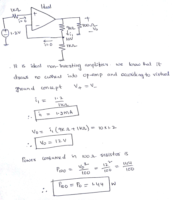
![[6] Find the current through 9㏀ resistor, n, the output voltage, vo, and the power consumed in the 100Ω load resistor, po. 1k2 Ideal 1.2V vo 100Ω i,](http://img.homeworklib.com/questions/6cba89e0-ce33-11ea-bc54-dd7b35a1455c.png?x-oss-process=image/resize,w_560)
Homework Answers
Add Answer to:
[6] Find the current through 9㏀ resistor, n, the output voltage, vo, and the power consumed...
Use the mesh current method to find the current I passing through the 20 resistor
 Figure Q1 shows a resistive circuit with an ideal DC voltage source.a) Use the mesh current method to find the current I passing through the resistor 20.b) calculate the power consumed by the 5 resistor
1. Find the ratio of the output voltage to the input voltage, Vo/Vin, in the circuit...
 1. Find the ratio of the output voltage to the input voltage, Vo/Vin, in the circuit shown. State your assumptions in using the ideal op-amp model. 15 k2 Vin 2. Find the output voltage Vo in the circuit shown assuming an ideal op-amp. State your assumptions in using the ideal op-amp model 15 k12 Vo . Find the voltage Vx and the output voltage Vo in the circuit shown assuming ideal op-amp 3 k2 1 V 6 kn 12 k2
9. In this ideal op amp circuit: a) Find the output voltage vo in terms of...
 9. In this ideal op amp circuit: a) Find the output voltage vo in terms of the input voltage v. b) The op amp is supplied by +10v and -10v. If0 V15v, find the range of the output voltage vo. (15 pts.) 10 k2 5 kQ 10V -10V ng 2.5v(+ 0)
Is N N Vo V's Vo Vs LOAD LOAD Figure 1 It has been shown in...
 Is N N Vo V's Vo Vs LOAD LOAD Figure 1 It has been shown in lectures that from the equality of power generation and power consumption, and as far as the average input/output voltages and currents are concerned, the buck and boost converters' operation in CCM (continuous current mode) are similar to the operation of the ideal AC transformers. So these converters may be considered as "ideal DC transformers". A buck converter operates with a duty cycle D 0.4,...
Find the current through and the voltage across each resistor in Fig. 6. Problem 10. Find...
 Find the current through and the voltage across each resistor in
Fig. 6.
Problem 10. Find the current through and the voltage across each resistor in Fig. 6. R1 152 ww V, 9.0 V R 102 R, 18 R, 35 Q V, 12 V Figure 6: Problem 10: Find the current through and the voltage across each resistor.
Find the current through and the voltage across each resistor in
Fig. 6.
Problem 10. Find the current through and the voltage across each resistor in Fig. 6. R1 152 ww V, 9.0 V R 102 R, 18 R, 35 Q V, 12 V Figure 6: Problem 10: Find the current through and the voltage across each resistor.
6) The power dissipated by a resistor with a current flowing through it is a) negative...
 6) The power dissipated by a resistor with a current flowing through it is a) negative d) depends on the direction of the voltage an current through the resistor e) none of the above b) zero e) positive
Answer: -771, -25.7, 5 mW, 99.2 mW 4–2 Find the voltage gain vo/vı and the current...
 Answer: -771, -25.7, 5 mW, 99.2 mW
4–2 Find the voltage gain vo/vı and the current gain io/is in Figure P4–2. For is = 10 mA, find the power supplied by the input current source and the power delivered to the 1.5-k 2 load resistor. + 6 + 100 S2 10032 | 9001 is 1 v 2ko } 1.5 kaš VO o FIGURE P4-2
Answer: -771, -25.7, 5 mW, 99.2 mW
4–2 Find the voltage gain vo/vı and the current gain io/is in Figure P4–2. For is = 10 mA, find the power supplied by the input current source and the power delivered to the 1.5-k 2 load resistor. + 6 + 100 S2 10032 | 9001 is 1 v 2ko } 1.5 kaš VO o FIGURE P4-2
7.2Ω 6Ω 2) For the circuit shown, find (a) the voltage Vo; (b) the power delivered...
 7.2Ω 6Ω 2) For the circuit shown, find (a) the voltage Vo; (b) the power delivered to the circuit by the current source; and (c) the power dissipated in the 10Ω resistor. Vo 300 64Ω 10Ω
1.5 Find the midpoint voltage, Vx, and output voltage, Vo, for the chain of two nMOS...
 1.5 Find the midpoint voltage, Vx, and output voltage, Vo, for the chain of two nMOS pass transistors shown below for the following cases. Assume VDD = 3.3V and Vtn = 0.5V. (a) V. = OV · (b) V;= 0.7V (c) V; = 1.2V (d) V. - 2.2V (e) V. = 3.3V Figure 3. Figure for Question 1.5.
7 2Ω 6Ω For the circuit shown, find (a) the voltage Vo, (b) the power delivered...
 7 2Ω 6Ω For the circuit shown, find (a) the voltage Vo, (b) the power delivered to the circuit by the current source; and (c) the power dissipated in the 10Ω resistor. 2) 5A Vo 30n 64Ω
 1. Find the ratio of the output voltage to the input voltage, Vo/Vin, in the circuit shown. State your assumptions in using the ideal op-amp model. 15 k2 Vin 2. Find the output voltage Vo in the circuit shown assuming an ideal op-amp. State your assumptions in using the ideal op-amp model 15 k12 Vo . Find the voltage Vx and the output voltage Vo in the circuit shown assuming ideal op-amp 3 k2 1 V 6 kn 12 k2
 9. In this ideal op amp circuit: a) Find the output voltage vo in terms of the input voltage v. b) The op amp is supplied by +10v and -10v. If0 V15v, find the range of the output voltage vo. (15 pts.) 10 k2 5 kQ 10V -10V ng 2.5v(+ 0)
 Is N N Vo V's Vo Vs LOAD LOAD Figure 1 It has been shown in lectures that from the equality of power generation and power consumption, and as far as the average input/output voltages and currents are concerned, the buck and boost converters' operation in CCM (continuous current mode) are similar to the operation of the ideal AC transformers. So these converters may be considered as "ideal DC transformers". A buck converter operates with a duty cycle D 0.4,...
 Find the current through and the voltage across each resistor in
Fig. 6.
Problem 10. Find the current through and the voltage across each resistor in Fig. 6. R1 152 ww V, 9.0 V R 102 R, 18 R, 35 Q V, 12 V Figure 6: Problem 10: Find the current through and the voltage across each resistor.
Find the current through and the voltage across each resistor in
Fig. 6.
Problem 10. Find the current through and the voltage across each resistor in Fig. 6. R1 152 ww V, 9.0 V R 102 R, 18 R, 35 Q V, 12 V Figure 6: Problem 10: Find the current through and the voltage across each resistor.
 6) The power dissipated by a resistor with a current flowing through it is a) negative d) depends on the direction of the voltage an current through the resistor e) none of the above b) zero e) positive
 Answer: -771, -25.7, 5 mW, 99.2 mW
4–2 Find the voltage gain vo/vı and the current gain io/is in Figure P4–2. For is = 10 mA, find the power supplied by the input current source and the power delivered to the 1.5-k 2 load resistor. + 6 + 100 S2 10032 | 9001 is 1 v 2ko } 1.5 kaš VO o FIGURE P4-2
Answer: -771, -25.7, 5 mW, 99.2 mW
4–2 Find the voltage gain vo/vı and the current gain io/is in Figure P4–2. For is = 10 mA, find the power supplied by the input current source and the power delivered to the 1.5-k 2 load resistor. + 6 + 100 S2 10032 | 9001 is 1 v 2ko } 1.5 kaš VO o FIGURE P4-2
 7.2Ω 6Ω 2) For the circuit shown, find (a) the voltage Vo; (b) the power delivered to the circuit by the current source; and (c) the power dissipated in the 10Ω resistor. Vo 300 64Ω 10Ω
 1.5 Find the midpoint voltage, Vx, and output voltage, Vo, for the chain of two nMOS pass transistors shown below for the following cases. Assume VDD = 3.3V and Vtn = 0.5V. (a) V. = OV · (b) V;= 0.7V (c) V; = 1.2V (d) V. - 2.2V (e) V. = 3.3V Figure 3. Figure for Question 1.5.
 7 2Ω 6Ω For the circuit shown, find (a) the voltage Vo, (b) the power delivered to the circuit by the current source; and (c) the power dissipated in the 10Ω resistor. 2) 5A Vo 30n 64Ω
Most questions answered within 3 hours.
-
An empty test tube weighs 15.923 grams. Then,
MgCl2•6H2O is added into the test tube. After...
asked 34 minutes ago -
Please answer true or false. Words
cannot be changed or added in to make it true...
asked 32 minutes ago -
(a) A piston at 6.1 atm contains a gas that occupies a volume of
3.5 L....
asked 33 minutes ago -
Assume memory access is 10 units of time and disk access is
10000 units of time....
asked 52 minutes ago -
1. Are all good samples random?
2. Magazines often report surveys giving statistics such as “63%...
asked 1 hour ago -
Under all the various types of market structures, firms
must eventually earn some economic profits for...
asked 1 hour ago -
Consider the following fitness regime for a single locus trait
with two co-dominant alleles: w11 =...
asked 1 hour ago -
A large cable company reports the following.
80% of its customers subscribe to its cable TV...
asked 1 hour ago -
Please answer the question in brief.
Discuss the role of ERP in organizations. Are ERP tools...
asked 1 hour ago -
Discuss the pros and cons of collaborative software such
as SameTime. Does it increase productivity? What...
asked 1 hour ago -
Buying your in-laws a gift because it’s expected is
due to the ____________ motive of gift-giving....
asked 1 hour ago -
Calculate the expected value, the variance, and the standard
deviation of the given random variable X....
asked 2 hours ago