
Homework Answers


Add Answer to:
A compound frame is subjected to a set of loads as shown in Figure 4 20...
1. (28 pts) A cantilever beam is subjected to the loads as shown in the figure....
 1. (28 pts) A cantilever beam is subjected to the loads as shown in the figure. Va) Draw a free-body diagram and determine the supports at point 0. b) Draw shear and moment diagrams and find the values at key points (i.e. x = 0, 6 and 10 ft). If possible, please show your calculations. c) Find shear force V(x) and bending moment M(x) for () <x<6 ft. 12 10 kip 2 kip/ft skip سے 40 kip.lt 611 4 11...
Questions 5-8 A steel frame shown below is subjected to combined uniformly distributed gravity load (w...
 Questions 5-8
A steel frame shown below is subjected to combined uniformly distributed gravity load (w 2 kips/f) and a horizontal earthquake load of H-10 kips Both the beams and the columns are made of W12x120 section having a yield strength of F 45 ksi. The Young's modulus of steel s E-29,000 ksi. The distributed load w is used to simulate the self-weight of the beam, the load transferred from roof slab, as well addition superimposed dead loads. The self-weigh...
Questions 5-8
A steel frame shown below is subjected to combined uniformly distributed gravity load (w 2 kips/f) and a horizontal earthquake load of H-10 kips Both the beams and the columns are made of W12x120 section having a yield strength of F 45 ksi. The Young's modulus of steel s E-29,000 ksi. The distributed load w is used to simulate the self-weight of the beam, the load transferred from roof slab, as well addition superimposed dead loads. The self-weigh...
Consider the structure and applied actions shown in the adjoining figure The frame is subjected to...
 Consider the structure and applied actions shown in the adjoining figure The frame is subjected to a uniformly distributed load on CD, a change in temperature in AB and support settlement at D. Use the dimensions and load values in the table below. Analyse the structure for all actions acting applied simultaneously and determine the reactions, member forces and displacement required in the table below. Enter your answers in the space provided. Dimensions 4 m 0.275lm 0.00001 Applied actions: DY...
PartA The compound beam shown in (Figure 1) is subjected to a uniform dead load of...
 PartA The compound beam shown in (Figure 1) is subjected to a uniform dead load of 300 lb/ft and a single live load of 2 k. Assume C is a fixed support, B is a pin, and A is a roller Determine the negative bending moment with the maximum magnitude created by these loads at C Express your answer using three significant figures (Mc)max(-) k ft Figure 1 of 1 Submit uest Answer Part B Determine the negative shear with...
Consider the beam subjected to a concentrated load consisting of 2.25 kips of dead load and...
 Consider the beam subjected to a concentrated load consisting of
2.25 kips of dead load and 5.55 kips of live load at point B. Find
maximum factored beam shear, moment, and deflection.
Consider the beam and loading given below. The beam is subjected to a concentrated load consisting of 2.25 kips of dead load and 5.55 kips of live load at point B. Neglect beam weight. You may use any information from the AISC Manual, a) Draw the general shape...
Consider the beam subjected to a concentrated load consisting of
2.25 kips of dead load and 5.55 kips of live load at point B. Find
maximum factored beam shear, moment, and deflection.
Consider the beam and loading given below. The beam is subjected to a concentrated load consisting of 2.25 kips of dead load and 5.55 kips of live load at point B. Neglect beam weight. You may use any information from the AISC Manual, a) Draw the general shape...
For the frame shown below: 1- Calculate the reactions at the supports. 2- Draw the Normal force, the Shear force and the Bending moment diagrams. Indicate all critical values 3- Show the equilibrium a...
 For the frame shown below:1- Calculate the reactions at the supports.2- Draw the Normal force, the Shear force and the Bending moment
diagrams. Indicate all critical values3- Show the equilibrium at node B.4- Develop the analytical expression for the normal force, the
shear force and the bending moment diagram for memberBC.The 4 Kips/ft load is applied perpendicular to member
AB.
For the frame shown below:1- Calculate the reactions at the supports.2- Draw the Normal force, the Shear force and the Bending moment
diagrams. Indicate all critical values3- Show the equilibrium at node B.4- Develop the analytical expression for the normal force, the
shear force and the bending moment diagram for memberBC.The 4 Kips/ft load is applied perpendicular to member
AB.
9. A beam ABC is subjected to a combination of UDL, point loads and applied moments...
 9. A beam ABC is subjected to a combination of UDL, point loads and applied moments as shown below. Draw to scale the shear force and bending moment diagrams. Label all local maximum and minimum values. Also sketch the deflected shape and indicate the location of any points of inflexion. (Ans: Moment at point D= 105kNm) 50 kNm 120 KN 20 kNm w = 10 kN/m BOTIT be 3 m 3 m 4 m Figure 5 Deflected shape Shear force...
P5.47. For the frame in Figure P5.47 . draw the shear and moment curves for all...
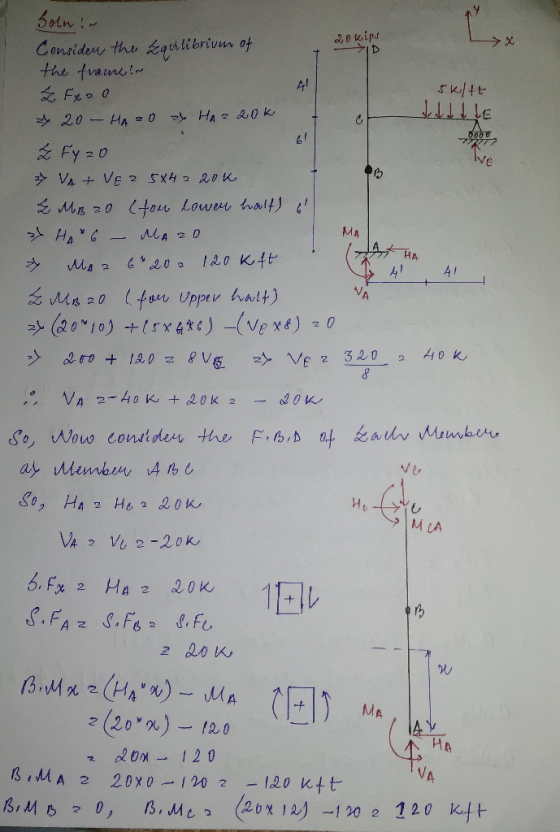
 P5.47. For the frame in Figure P5.47 . draw the shear and moment curves for all members. Next sketch the deflected shape of the frame. Show all forces acting on a free-body diagram of joint C. 20 kips W = 5 kips/ft E B hinge P5,47
The beam shown in Figure (2) is subjected to a uniform live load of 2.4 kN/m,...
 The beam shown in Figure (2) is subjected to a uniform live load of 2.4 kN/m, a dead load of 1.0 kN/m, and a single live load of 80 kN. Assume B is an internal hinge. Determine: (a) the maximum positive moment at E, (b) the maximum positive shear at E. created by these loads. Hinge A B С E D 2m 2m 2m 2m
The distributed loads and couple act on the frame shown in the figure. Determine the following:...
 The distributed loads and couple act on the frame shown in the figure. Determine the following: a) Reduce the load system into a single resultant force and resulting moment acting at point B. b) Reduce this load system to a single resultant force and determine where this resultants line of action intersects member BC, measured from C.
 1. (28 pts) A cantilever beam is subjected to the loads as shown in the figure. Va) Draw a free-body diagram and determine the supports at point 0. b) Draw shear and moment diagrams and find the values at key points (i.e. x = 0, 6 and 10 ft). If possible, please show your calculations. c) Find shear force V(x) and bending moment M(x) for () <x<6 ft. 12 10 kip 2 kip/ft skip سے 40 kip.lt 611 4 11...
 Questions 5-8
A steel frame shown below is subjected to combined uniformly distributed gravity load (w 2 kips/f) and a horizontal earthquake load of H-10 kips Both the beams and the columns are made of W12x120 section having a yield strength of F 45 ksi. The Young's modulus of steel s E-29,000 ksi. The distributed load w is used to simulate the self-weight of the beam, the load transferred from roof slab, as well addition superimposed dead loads. The self-weigh...
Questions 5-8
A steel frame shown below is subjected to combined uniformly distributed gravity load (w 2 kips/f) and a horizontal earthquake load of H-10 kips Both the beams and the columns are made of W12x120 section having a yield strength of F 45 ksi. The Young's modulus of steel s E-29,000 ksi. The distributed load w is used to simulate the self-weight of the beam, the load transferred from roof slab, as well addition superimposed dead loads. The self-weigh...
 Consider the structure and applied actions shown in the adjoining figure The frame is subjected to a uniformly distributed load on CD, a change in temperature in AB and support settlement at D. Use the dimensions and load values in the table below. Analyse the structure for all actions acting applied simultaneously and determine the reactions, member forces and displacement required in the table below. Enter your answers in the space provided. Dimensions 4 m 0.275lm 0.00001 Applied actions: DY...
 PartA The compound beam shown in (Figure 1) is subjected to a uniform dead load of 300 lb/ft and a single live load of 2 k. Assume C is a fixed support, B is a pin, and A is a roller Determine the negative bending moment with the maximum magnitude created by these loads at C Express your answer using three significant figures (Mc)max(-) k ft Figure 1 of 1 Submit uest Answer Part B Determine the negative shear with...
 Consider the beam subjected to a concentrated load consisting of
2.25 kips of dead load and 5.55 kips of live load at point B. Find
maximum factored beam shear, moment, and deflection.
Consider the beam and loading given below. The beam is subjected to a concentrated load consisting of 2.25 kips of dead load and 5.55 kips of live load at point B. Neglect beam weight. You may use any information from the AISC Manual, a) Draw the general shape...
Consider the beam subjected to a concentrated load consisting of
2.25 kips of dead load and 5.55 kips of live load at point B. Find
maximum factored beam shear, moment, and deflection.
Consider the beam and loading given below. The beam is subjected to a concentrated load consisting of 2.25 kips of dead load and 5.55 kips of live load at point B. Neglect beam weight. You may use any information from the AISC Manual, a) Draw the general shape...
 For the frame shown below:1- Calculate the reactions at the supports.2- Draw the Normal force, the Shear force and the Bending moment
diagrams. Indicate all critical values3- Show the equilibrium at node B.4- Develop the analytical expression for the normal force, the
shear force and the bending moment diagram for memberBC.The 4 Kips/ft load is applied perpendicular to member
AB.
For the frame shown below:1- Calculate the reactions at the supports.2- Draw the Normal force, the Shear force and the Bending moment
diagrams. Indicate all critical values3- Show the equilibrium at node B.4- Develop the analytical expression for the normal force, the
shear force and the bending moment diagram for memberBC.The 4 Kips/ft load is applied perpendicular to member
AB.
 9. A beam ABC is subjected to a combination of UDL, point loads and applied moments as shown below. Draw to scale the shear force and bending moment diagrams. Label all local maximum and minimum values. Also sketch the deflected shape and indicate the location of any points of inflexion. (Ans: Moment at point D= 105kNm) 50 kNm 120 KN 20 kNm w = 10 kN/m BOTIT be 3 m 3 m 4 m Figure 5 Deflected shape Shear force...
 P5.47. For the frame in Figure P5.47 . draw the shear and moment curves for all members. Next sketch the deflected shape of the frame. Show all forces acting on a free-body diagram of joint C. 20 kips W = 5 kips/ft E B hinge P5,47
 The beam shown in Figure (2) is subjected to a uniform live load of 2.4 kN/m, a dead load of 1.0 kN/m, and a single live load of 80 kN. Assume B is an internal hinge. Determine: (a) the maximum positive moment at E, (b) the maximum positive shear at E. created by these loads. Hinge A B С E D 2m 2m 2m 2m
Most questions answered within 3 hours.
-
Steven can afford car payments of $300 a month for 72 months.
The bank will lend...
asked 15 minutes ago -
Embedded
System..
1.
Analyze
the instruction
sets below.
LDR R1, [R0,
#0x08]
SUB R1, R1,
R2,...
asked 19 minutes ago -
Use proper sentence structure to communicate clearly.
Choose the correct sentence structure in each of the...
asked 19 minutes ago -
There are investors who claim they only invest in companies with
great products and outstanding management,...
asked 22 minutes ago -
what is employee/ employer relations ?
why is Employee/ Employer relation is important in the context...
asked 40 minutes ago -
Explain the relationship between tests of acquisition and
payment cycle and tests of accounts payable. Give...
asked 38 minutes ago -
A hot-air balloon is descending with a velocity of (−2.00m/s)y^.
A champagne bottle is opened to...
asked 57 minutes ago -
1. When a nearsighted person looks at an object that is in the
distance with their...
asked 2 hours ago -
QUESTION 8
Both of these statements will store the same value in the
variable $number
$number...
asked 2 hours ago -
The price of 1 lb of potatoes is $1.75. If all the potatoes sold
today at...
asked 3 hours ago -
Garcia Company issues 20.00%, 15-year bonds with a par value of
$470,000 and semiannual interest payments....
asked 3 hours ago -
In C++ Programming, Try using loops only.
This lab demonstrates the use of the While Loop...
asked 4 hours ago