
Homework Answers
Add Answer to:
A composite bar is made from two materials (shown below), is subjected to a temperature increase...
A composite bar is made from two materials (shown below), is subjected to a temperature increase...
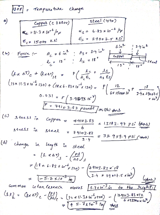
 A composite bar is made from two materials (shown below), is subjected to a temperature increase of 120 °F. Complete the following. a) Provide a table showing material properties relevant to the problem (e.g. Young's Modulus etc.) b) Using information from above determine the force at the unyielding supports c) Determine the stress in each material d) Determine the displacement and final position of the common interface Common interface 6 in2 2.4 in Unyielding support Steel (4140) Unyielding support Copper...
A composite bar is made from two materials (shown below), is subjected Complete the following. a)...
 A composite bar is made from two materials (shown below), is subjected Complete the following. a) Provide a table showing material properties relevant to the problem (e.g. Young's Modulus etc.) b) Using information from above determine the force at the unyielding supports c) Determine the stress in each material d) Determine the displacement and final position of the common interface to a temperature increase of 120 °F Common interface 6 in2 2.4 in2 Unyielding support Steel (4140) Copper (C26800) Unyielding...
The composite shaft, consisting of aluminum, copper, and steel sections, is subjected to the loading shown....
 The composite shaft, consisting of aluminum, copper, and steel sections, is subjected to the loading shown. Determine the displacement of end A with respect to end D and the normal stress in each section. The cross-sectional Aluminum Соpper Steel E=10(10') ksi AAB 0.09 in2 Eg=18(10') ksi ARc 0.12 in2 E-29(10) ksi ACD 0.06 in 1.75 kip 3.50 kip 1.50 kip 2.00 kip area and modulus of elasticity for each section are shown in the figure. Neglect the size of the...
The composite shaft, consisting of aluminum, copper, and steel sections, is subjected to the loading shown....
 The composite shaft, consisting of aluminum, copper, and steel sections, is subjected to the loading shown. The cross-sectional areas of sections AB, BC ,and CD are AAB 0.10 in2 , ABC 0.11 in2 , and AcD =0.07 in2 , respectively. The modulus of elasticity for each section are shown in the figure. Neglect the size of the collars at B and C Part A Determine the displacement of B with respect to C of the composite shaft. Express your answer...
A long composite hollow cylinder (L >> 2c) is subjected to an internal pressure, p, as...
 A long composite hollow cylinder (L >> 2c) is subjected to an internal pressure, p, as shown in the figure. Assuming idealized perfect bonding between the two materials, the normal stress and displacement will be continuous across the interface atr b. Determine the stress and displacement fields in each material. Assume isotropic material properties El, v, and E2, V2 (30 pts) 2a Material2 Material 1 2b 2C
Problem 3: Composite moduli Composites are materials that are composed of two or more distinct composed...
 Problem 3: Composite moduli Composites are materials that are composed of two or more distinct composed of two materials with Young's modulus E, (top and bottom components) and Eb (center component), and where 0 < λ < 1. HAL (1-A)L AL Ex (3a) Suppose that the material is subjected to an average stress σχ along the x direction resulting in a strain Ex as shown in the center figure above. Find the effective Young's modulus Eer (in terms of E....
The composite cantilever shown below is made of three plates: two external ones are made of...
 The composite cantilever shown
below is made of three plates: two external ones are made of steel
and the middle one is made of copper. The length of the cantilever
is 2m, the width is 50mm, and the thickness of each plate is 20mm.
Determine the axial force induced in the copper plate when the
temperature of the cantilever rises by 77°C. Young's modulus for
steel can be taken as 200GPa and the coefficient of thermal
expansion as 11x10-6mm/(mm oC)....
The composite cantilever shown
below is made of three plates: two external ones are made of steel
and the middle one is made of copper. The length of the cantilever
is 2m, the width is 50mm, and the thickness of each plate is 20mm.
Determine the axial force induced in the copper plate when the
temperature of the cantilever rises by 77°C. Young's modulus for
steel can be taken as 200GPa and the coefficient of thermal
expansion as 11x10-6mm/(mm oC)....
The composite shaft, consisting of aluminum, copper, and steel sections, is subjected to the loading shown. The cross-se...
 The composite shaft, consisting of aluminum, copper, and steel
sections, is subjected to the loading shown. The cross-sectional
areas of sections AB, BC , and CD are
AAB = 0.08 in2 , ABC = 0.15
in2 , and ACD = 0.05 in2 ,
respectively. The modulus of elasticity for each section are shown
in the figure. Neglect the size of the collars at B and C.
(Figure 1)
Part A
Determine the normal stress in section AB.
Express your answer...
The composite shaft, consisting of aluminum, copper, and steel
sections, is subjected to the loading shown. The cross-sectional
areas of sections AB, BC , and CD are
AAB = 0.08 in2 , ABC = 0.15
in2 , and ACD = 0.05 in2 ,
respectively. The modulus of elasticity for each section are shown
in the figure. Neglect the size of the collars at B and C.
(Figure 1)
Part A
Determine the normal stress in section AB.
Express your answer...
Q5. The cantilever beam, AC, is subjected to the load case shown in Figure 5. For the loading shown, do the following: [10 Marks] a) Calculate the magnitude and direction of the reactions at A b) Usi...
 Q5. The cantilever beam, AC, is subjected to the load case shown in Figure 5. For the loading shown, do the following: [10 Marks] a) Calculate the magnitude and direction of the reactions at A b) Using the Macaulay function, determine the displacement in y of the point B of the beam (x 2.4 m from the support at A) [10 Marks] c) Determine the slope at B. [5 Marks] The beam has a Young's modulus of E-200 GPa and...
 A composite bar is made from two materials (shown below), is subjected to a temperature increase of 120 °F. Complete the following. a) Provide a table showing material properties relevant to the problem (e.g. Young's Modulus etc.) b) Using information from above determine the force at the unyielding supports c) Determine the stress in each material d) Determine the displacement and final position of the common interface Common interface 6 in2 2.4 in Unyielding support Steel (4140) Unyielding support Copper...
 A composite bar is made from two materials (shown below), is subjected Complete the following. a) Provide a table showing material properties relevant to the problem (e.g. Young's Modulus etc.) b) Using information from above determine the force at the unyielding supports c) Determine the stress in each material d) Determine the displacement and final position of the common interface to a temperature increase of 120 °F Common interface 6 in2 2.4 in2 Unyielding support Steel (4140) Copper (C26800) Unyielding...
 The composite shaft, consisting of aluminum, copper, and steel sections, is subjected to the loading shown. Determine the displacement of end A with respect to end D and the normal stress in each section. The cross-sectional Aluminum Соpper Steel E=10(10') ksi AAB 0.09 in2 Eg=18(10') ksi ARc 0.12 in2 E-29(10) ksi ACD 0.06 in 1.75 kip 3.50 kip 1.50 kip 2.00 kip area and modulus of elasticity for each section are shown in the figure. Neglect the size of the...
 The composite shaft, consisting of aluminum, copper, and steel sections, is subjected to the loading shown. The cross-sectional areas of sections AB, BC ,and CD are AAB 0.10 in2 , ABC 0.11 in2 , and AcD =0.07 in2 , respectively. The modulus of elasticity for each section are shown in the figure. Neglect the size of the collars at B and C Part A Determine the displacement of B with respect to C of the composite shaft. Express your answer...
 The composite shaft, consisting of aluminum, copper, and steel sections, is subjected to the loading shown. The cross-sectional areas of sections AB, BC ,and CD are AAB 0.10 in2 , ABC 0.11 in2 , and AcD =0.07 in2 , respectively. The modulus of elasticity for each section are shown in the figure. Neglect the size of the collars at B and C Part A Determine the displacement of B with respect to C of the composite shaft. Express your answer...
 A long composite hollow cylinder (L >> 2c) is subjected to an internal pressure, p, as shown in the figure. Assuming idealized perfect bonding between the two materials, the normal stress and displacement will be continuous across the interface atr b. Determine the stress and displacement fields in each material. Assume isotropic material properties El, v, and E2, V2 (30 pts) 2a Material2 Material 1 2b 2C
 Problem 3: Composite moduli Composites are materials that are composed of two or more distinct composed of two materials with Young's modulus E, (top and bottom components) and Eb (center component), and where 0 < λ < 1. HAL (1-A)L AL Ex (3a) Suppose that the material is subjected to an average stress σχ along the x direction resulting in a strain Ex as shown in the center figure above. Find the effective Young's modulus Eer (in terms of E....
 The composite cantilever shown
below is made of three plates: two external ones are made of steel
and the middle one is made of copper. The length of the cantilever
is 2m, the width is 50mm, and the thickness of each plate is 20mm.
Determine the axial force induced in the copper plate when the
temperature of the cantilever rises by 77°C. Young's modulus for
steel can be taken as 200GPa and the coefficient of thermal
expansion as 11x10-6mm/(mm oC)....
The composite cantilever shown
below is made of three plates: two external ones are made of steel
and the middle one is made of copper. The length of the cantilever
is 2m, the width is 50mm, and the thickness of each plate is 20mm.
Determine the axial force induced in the copper plate when the
temperature of the cantilever rises by 77°C. Young's modulus for
steel can be taken as 200GPa and the coefficient of thermal
expansion as 11x10-6mm/(mm oC)....
 The composite shaft, consisting of aluminum, copper, and steel
sections, is subjected to the loading shown. The cross-sectional
areas of sections AB, BC , and CD are
AAB = 0.08 in2 , ABC = 0.15
in2 , and ACD = 0.05 in2 ,
respectively. The modulus of elasticity for each section are shown
in the figure. Neglect the size of the collars at B and C.
(Figure 1)
Part A
Determine the normal stress in section AB.
Express your answer...
The composite shaft, consisting of aluminum, copper, and steel
sections, is subjected to the loading shown. The cross-sectional
areas of sections AB, BC , and CD are
AAB = 0.08 in2 , ABC = 0.15
in2 , and ACD = 0.05 in2 ,
respectively. The modulus of elasticity for each section are shown
in the figure. Neglect the size of the collars at B and C.
(Figure 1)
Part A
Determine the normal stress in section AB.
Express your answer...
 Q5. The cantilever beam, AC, is subjected to the load case shown in Figure 5. For the loading shown, do the following: [10 Marks] a) Calculate the magnitude and direction of the reactions at A b) Using the Macaulay function, determine the displacement in y of the point B of the beam (x 2.4 m from the support at A) [10 Marks] c) Determine the slope at B. [5 Marks] The beam has a Young's modulus of E-200 GPa and...
Most questions answered within 3 hours.
-
Cost and fair value data for the trading debt securities of
Wildhorse Company at December 31,...
asked 14 minutes ago -
In a population of jaguars, a gene with two alleles encodes the
fur color. Allele B...
asked 1 hour ago -
Two copper wires, one 1.80 times the diameter of the other, have
the same current flowing...
asked 1 hour ago -
9. In 2003 the price of ‘home heating oil’ substantially
increased during the harsh winter. In...
asked 1 hour ago -
Match the key paradoxes of negotiation.
Claiming Value
Sticking by your principles
Sticking with your strategy...
asked 2 hours ago -
Question text Suppose a sample of 28 observations is taken from
a population, and the sample...
asked 3 hours ago -
The mayor of a small town estimates that 33% of the
residents in the town favor...
asked 3 hours ago -
1. True or false: According to the Gordon Growth Model, firms
that pay dividends will always...
asked 4 hours ago -
20
Lansing Corporation reported net income of $67 million for last
year. Depreciation expense totaled $15...
asked 4 hours ago -
Write a MATLAB userdefined function that calculates the product and
the ratio of two variables x...
asked 4 hours ago -
Timia needs some cash in a hurry. She owns her car outright and
is considering a...
asked 4 hours ago -
A sweepstakes posted the probabilities of winning each prize and
the prize amounts as shown in...
asked 4 hours ago