
Homework Answers

Add Answer to:
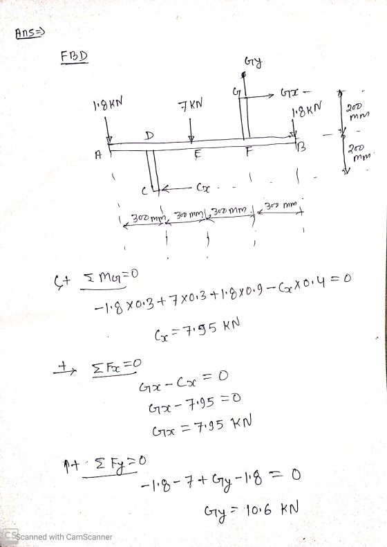
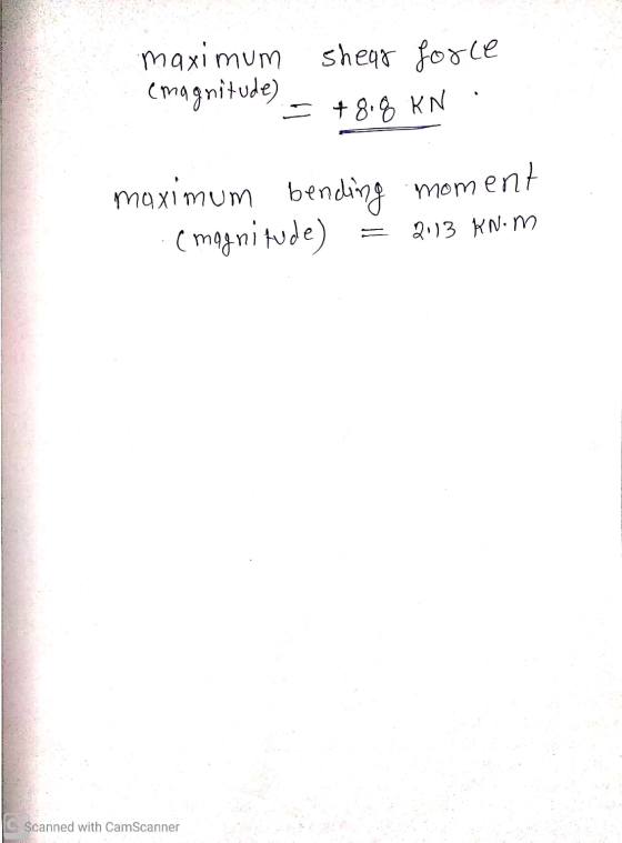
Question 3 For the following beam structure, draw the bending moment and shear force diagrams. Also,...
4. For the beam and loading shown, draw the shear force and bending moment diagrams and...
 4. For the beam and loading shown, draw the shear force and bending moment diagrams and determine the maximum bending and shear force and their locations. 20 KN 40 KN B D 250 mm |--2.5 m- 3m-4-2 m 80 mm 5. For the beam and loading shown, draw the shear force and bending moment diagrams and determine the maximum bending and shear force and their locations. 50 KN
Q1. Draw the shear force and bending moment diagrams for the following cantilever beam
 Q1. Draw the shear force and bending moment diagrams for the following cantilever beam (10 marks). Q2. Draw the shear force and bending moment diagrams for the following simply supported beam (10 marks). Q3. Draw the shear force and bending moment diagrams for the following simply supported beam with cantilever extension (15 marks). Q4. Draw the shear force and bending moment diagrams for the following compound beam (15 marks).
Draw shear force and bending moment diagrams of the following beam structure with an internal hinge
 Draw shear force and bending moment diagrams of the following beam
structure with an internal hinge
Draw shear force and bending moment diagrams of the following beam
structure with an internal hinge
Draw the shear and bending-moment diagrams for the beam and loading shown.
 Required information Consider the given beam and loading. Draw the shear and bending-moment diagrams for the beam and loading shown.Determine the maximum absolute values of the shear and bending moment. (Round the final answer to one decimal place.) The maximum absolute shear force is _______ KN. The maximum absolute bending moment is _______ kN.m.
(35 points) (a) Draw the shear and bending moment diagrams for the cantilever beam shown. (b)...
 (35 points) (a) Draw the shear and bending moment diagrams for the cantilever beam shown. (b) Specify the maximum positive and negative shear force and bending moment. Take L1 300 mm, L2 -300 mm, q 100 N/m. 2.
For the following diagram, draw the shear and bending moment diagrams for the beam. Include the shear force and bending moment equations.
 For the following diagram, draw the shear and bending moment diagrams for the beam. Include the shear force and bending moment equations.
For the beam and loading shown draw the shear and bending moment diagrams and then find...
 For the beam and loading shown draw the shear and bending moment
diagrams and then find the maximum absolute values of the shear and
bending moment.
1. For the beam and loading shown draw the shear and bending-moment diagrams and then find the maximum absolute values of the shear and bending moment. 300 N/m 4 m
For the beam and loading shown draw the shear and bending moment
diagrams and then find the maximum absolute values of the shear and
bending moment.
1. For the beam and loading shown draw the shear and bending-moment diagrams and then find the maximum absolute values of the shear and bending moment. 300 N/m 4 m
For the beam shown, draw the shear and bending moment diagrams and determine the magnitude and...
 For the beam shown, draw the shear and bending moment diagrams and determine the magnitude and location of the maximum absolute values of bending moment knowing that a) M 0, b) M 12 kNm.(7, 30) 20 kN/m С В М A 2m- 2 m
For the beam and loading shown, draw the shear and bending moment diagrams, and determine the...
 For the beam and loading shown, draw the shear and bending moment diagrams, and determine the magnitude and location of the maximum shear and bending moment. 2 kN/m AC D 6 NT 3kN/m lm-- 1.2 m 0.6 m
QUESTION 4 4. Bending Moment in a Beam Draw the shear and bending moment diagrams for...
 QUESTION 4 4. Bending Moment in a Beam Draw the shear and bending moment diagrams for the beam and loading shown. Then use the bending moment diagram to determine the bending moment in ſkip-ft] experienced by the beam at point D. 12 kips 12 kips 10 kips the С - 5 ft 5ft --- 2 ft 3 ft
 4. For the beam and loading shown, draw the shear force and bending moment diagrams and determine the maximum bending and shear force and their locations. 20 KN 40 KN B D 250 mm |--2.5 m- 3m-4-2 m 80 mm 5. For the beam and loading shown, draw the shear force and bending moment diagrams and determine the maximum bending and shear force and their locations. 50 KN
 Draw shear force and bending moment diagrams of the following beam
structure with an internal hinge
Draw shear force and bending moment diagrams of the following beam
structure with an internal hinge
 (35 points) (a) Draw the shear and bending moment diagrams for the cantilever beam shown. (b) Specify the maximum positive and negative shear force and bending moment. Take L1 300 mm, L2 -300 mm, q 100 N/m. 2.
 For the beam and loading shown draw the shear and bending moment
diagrams and then find the maximum absolute values of the shear and
bending moment.
1. For the beam and loading shown draw the shear and bending-moment diagrams and then find the maximum absolute values of the shear and bending moment. 300 N/m 4 m
For the beam and loading shown draw the shear and bending moment
diagrams and then find the maximum absolute values of the shear and
bending moment.
1. For the beam and loading shown draw the shear and bending-moment diagrams and then find the maximum absolute values of the shear and bending moment. 300 N/m 4 m
 For the beam shown, draw the shear and bending moment diagrams and determine the magnitude and location of the maximum absolute values of bending moment knowing that a) M 0, b) M 12 kNm.(7, 30) 20 kN/m С В М A 2m- 2 m
 For the beam and loading shown, draw the shear and bending moment diagrams, and determine the magnitude and location of the maximum shear and bending moment. 2 kN/m AC D 6 NT 3kN/m lm-- 1.2 m 0.6 m
 QUESTION 4 4. Bending Moment in a Beam Draw the shear and bending moment diagrams for the beam and loading shown. Then use the bending moment diagram to determine the bending moment in ſkip-ft] experienced by the beam at point D. 12 kips 12 kips 10 kips the С - 5 ft 5ft --- 2 ft 3 ft
Most questions answered within 3 hours.
-
Write the ionic equations for the first stage of salts
hydrolysis.
Anion, Cation?
Na2S
NiSO4
K2SO4...
asked 1 hour ago -
suppose there is a normally distributed population with a mean of
250 and a standard deviation...
asked 2 hours ago -
Question Three
Suppose you as project manager are using the Waterfall
development methodology on a large...
asked 3 hours ago -
Which statement is not true about welfare in Canada?
A.Benefits typically vary based on one's ability...
asked 3 hours ago -
Please help me with FLOWCHART and UML diagram for class,
thank you!
#include <iostream>
#include <fstream>...
asked 4 hours ago -
3. Describe the “logic circuit” of the Lac operon. Which
proteins are bound or not to...
asked 4 hours ago -
Ayesha’s adjusted gross income is $60,000 in 2019. She donated a
piece of artwork with a...
asked 4 hours ago -
For Dijkstra’s shortest path algorithm:
a. Give the Big-O time for Dijkstra’s shortest path algorithm
and...
asked 4 hours ago -
Phosphorus violates the 'octet rule' in biological molecules,
forming more covalent bonds than expected based on...
asked 4 hours ago -
A 1.3 eV electron has a 10-4 probability of tunneling
through a 2.4 eV potential barrier....
asked 5 hours ago -
What is the one ingredient that is common to being successful
with all stakeholders?
profit
trust...
asked 5 hours ago -
Write an assembly language 32 bit program that reads in lines of
text by a .txt...
asked 5 hours ago