
Homework Answers
Add Answer to:
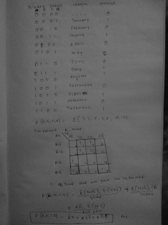
A circuit takes a 4-bit input F=f(a,b,c,d) representing the months January (0001) through December (1100). The...
(a) Write a truth table. The input is 4-bit binary ABCD, A is MSB, D is...
 (a) Write a truth table. The input is 4-bit binary ABCD, A is
MSB, D is LSB. The output is also represented by x.
(b) Obtain an output expression in the form of a SOP.
(c) Use Boolean Algebra to design a circuit consisting of only
four inverters, four 3-input and gate, and one 4-input OR gate
using the simplified and simplified expression obtained in (b).
4-6. The Excess-3 coding system is a four-bit digital coding system for encoding all...
(a) Write a truth table. The input is 4-bit binary ABCD, A is
MSB, D is LSB. The output is also represented by x.
(b) Obtain an output expression in the form of a SOP.
(c) Use Boolean Algebra to design a circuit consisting of only
four inverters, four 3-input and gate, and one 4-input OR gate
using the simplified and simplified expression obtained in (b).
4-6. The Excess-3 coding system is a four-bit digital coding system for encoding all...
Design a circuit that has a 3 bit binary input (representing 0 through 7) and outputs...
Design a circuit that has a 3 bit binary input (representing 0 through 7) and outputs a 1 if the input is a prime number. A prime number (or prime) is a natural number greater than 1 that has no positive divisors other than 1 and itself. a) Fill out a truth table that represents the logic equation for this circuit: Y = F(A,B,C). b) Using a Karnaugh map simplify the logic equation.
The circuit below takes as input a four bit unsigned binary number A A2 A Ao and generates a single output F. Design th...
 The circuit below takes as input a four bit unsigned binary number A A2 A Ao and generates a single output F. Design the circuit where F will only be true if the decimal value of the input mod 3 is equal to 1 (F is true if the input mod 3- 1; F will be false otherwise). To implement F, you may use only the 8 x 1 multiplexor given below. You may not use any additional gates (such...
Can you use Multisim or something similar. I got the truth table and design, but having...
 Can you use Multisim or something similar. I got the truth table
and design, but having a hard time with the actual wiring.
I need to see where each cable and light bulb go.
3.4. Multiplexer Multiplexers are very useful components in digital systems. They transfer a large number of information units over a smaller number of channels, (usually one channel) under the control of selection signals. Fig. 3 is a 4-line to l-line MUX. In this circuit, lo, 11, 12,...
Can you use Multisim or something similar. I got the truth table
and design, but having a hard time with the actual wiring.
I need to see where each cable and light bulb go.
3.4. Multiplexer Multiplexers are very useful components in digital systems. They transfer a large number of information units over a smaller number of channels, (usually one channel) under the control of selection signals. Fig. 3 is a 4-line to l-line MUX. In this circuit, lo, 11, 12,...
Q4) Write a VHDL module that implements a combinational circuit that indicates the number of days in a given month. Notes: The month input is a single port (4-bit number). 'The Leap_Year port...
 Q4) Write a VHDL module that implements a combinational circuit that indicates the number of days in a given month. Notes: The month input is a single port (4-bit number). 'The Leap_Year port indicate if it is a leap year. The outputs must be 4 separate ports. Invalid months should result in no outputs active.
Q4) Write a VHDL module that implements a combinational circuit that indicates the number of days in a given month. Notes: The month input is...
Q4) Write a VHDL module that implements a combinational circuit that indicates the number of days in a given month. Notes: The month input is a single port (4-bit number). 'The Leap_Year port indicate if it is a leap year. The outputs must be 4 separate ports. Invalid months should result in no outputs active.
Q4) Write a VHDL module that implements a combinational circuit that indicates the number of days in a given month. Notes: The month input is...
ECE 1552- Summer 2019 Homework 2: Solve all questions. HW is to be turned in as a PDF or word document on canvas. Show...
 ECE 1552- Summer 2019 Homework 2: Solve all questions. HW is to be turned in as a PDF or word document on canvas. Show all working. Answers provided should be typed or written CLEARLY 1: Find a function to detect an error in the representation of a decimal digit in BCD. In other words, write an equation with value 1 when the inputs are any one of the six unused bit combinations in the BCD code, and value 0 otherwise...
Problem 1: consider the following circuit with 4 inputs A, B, c, D, and 3 outputs...
 Problem 1:
consider the following circuit with 4 inputs A, B, c, D, and 3 outputs F, G, H. Each input/output is connected to an input/output port. 3-input OR gate Figure 1 a) Determine the Boolean algebra equations relating each input to each output of the circuit. b) Create the truth tables corresponding to the equations obtained above. There should be one truth table per equation c) Produce the Karnaugh maps corresponding to the truth tables d) Determine simplified Boolean...
Problem 1:
consider the following circuit with 4 inputs A, B, c, D, and 3 outputs F, G, H. Each input/output is connected to an input/output port. 3-input OR gate Figure 1 a) Determine the Boolean algebra equations relating each input to each output of the circuit. b) Create the truth tables corresponding to the equations obtained above. There should be one truth table per equation c) Produce the Karnaugh maps corresponding to the truth tables d) Determine simplified Boolean...
1. (15 pts) Simplify the following Boolean functions using K-maps: a. F(x,y,z) = (1,4,5,6,7) b. F(x,...
 1. (15 pts) Simplify the following Boolean functions using K-maps: a. F(x,y,z) = (1,4,5,6,7) b. F(x, y, z) = (xy + xyz + xyz c. F(A,B,C,D) = 20,2,4,5,6,7,8,10,13,15) d. F(A,B,C,D) = A'B'C'D' + AB'C + B'CD' + ABCD' + BC'D e. F(A,B,C,D,E) = (0,1,4,5,16,17,21,25,29) 2. (12 pts) Consider the combinational logic circuit below and answer the following: a. Derive the Boolean expressions for Fi and F2 as functions of A, B, C, and D. b. List the complete truth table...
Finite state machine (FSM) counter design: Gray codes have a useful property in that consecutive numbers differ in only a single bit position. Table 1 lists a 3-bit modulo 8 Gray code representing the...
 Finite state machine (FSM) counter design: Gray
codes have a useful property in that consecutive numbers differ in
only a single bit position. Table 1 lists a 3-bit modulo 8 Gray
code representing the numbers 0 to 7. Design a 3-bit modulo 8 Gray
code counter FSM.
a) First design and sketch a 3-bit modulo 8 Gray code counter
FSM with no inputs and three outputs, the 3-bit signal
Q2:0. (A modulo N counter counts from 0 to N −...
Finite state machine (FSM) counter design: Gray
codes have a useful property in that consecutive numbers differ in
only a single bit position. Table 1 lists a 3-bit modulo 8 Gray
code representing the numbers 0 to 7. Design a 3-bit modulo 8 Gray
code counter FSM.
a) First design and sketch a 3-bit modulo 8 Gray code counter
FSM with no inputs and three outputs, the 3-bit signal
Q2:0. (A modulo N counter counts from 0 to N −...
You will build a seven-segment display decoder, shown in Figure 3. The circuit has four input...
You will build a seven-segment display decoder, shown in Figure 3. The circuit has four input bits, D3:0 (representing a hexadecimal number between 0 and F), and produces seven output bits, Sa:g, that drive the seven segments to display the number. The 7-segment display we will use in this lab is a common cathode type, a segment of the display turns on when it is 1. The other type of 7-segment display is common anode, for which a segment turns...
 (a) Write a truth table. The input is 4-bit binary ABCD, A is
MSB, D is LSB. The output is also represented by x.
(b) Obtain an output expression in the form of a SOP.
(c) Use Boolean Algebra to design a circuit consisting of only
four inverters, four 3-input and gate, and one 4-input OR gate
using the simplified and simplified expression obtained in (b).
4-6. The Excess-3 coding system is a four-bit digital coding system for encoding all...
(a) Write a truth table. The input is 4-bit binary ABCD, A is
MSB, D is LSB. The output is also represented by x.
(b) Obtain an output expression in the form of a SOP.
(c) Use Boolean Algebra to design a circuit consisting of only
four inverters, four 3-input and gate, and one 4-input OR gate
using the simplified and simplified expression obtained in (b).
4-6. The Excess-3 coding system is a four-bit digital coding system for encoding all...
 The circuit below takes as input a four bit unsigned binary number A A2 A Ao and generates a single output F. Design the circuit where F will only be true if the decimal value of the input mod 3 is equal to 1 (F is true if the input mod 3- 1; F will be false otherwise). To implement F, you may use only the 8 x 1 multiplexor given below. You may not use any additional gates (such...
 Can you use Multisim or something similar. I got the truth table
and design, but having a hard time with the actual wiring.
I need to see where each cable and light bulb go.
3.4. Multiplexer Multiplexers are very useful components in digital systems. They transfer a large number of information units over a smaller number of channels, (usually one channel) under the control of selection signals. Fig. 3 is a 4-line to l-line MUX. In this circuit, lo, 11, 12,...
Can you use Multisim or something similar. I got the truth table
and design, but having a hard time with the actual wiring.
I need to see where each cable and light bulb go.
3.4. Multiplexer Multiplexers are very useful components in digital systems. They transfer a large number of information units over a smaller number of channels, (usually one channel) under the control of selection signals. Fig. 3 is a 4-line to l-line MUX. In this circuit, lo, 11, 12,...
 Q4) Write a VHDL module that implements a combinational circuit that indicates the number of days in a given month. Notes: The month input is a single port (4-bit number). 'The Leap_Year port indicate if it is a leap year. The outputs must be 4 separate ports. Invalid months should result in no outputs active.
Q4) Write a VHDL module that implements a combinational circuit that indicates the number of days in a given month. Notes: The month input is...
Q4) Write a VHDL module that implements a combinational circuit that indicates the number of days in a given month. Notes: The month input is a single port (4-bit number). 'The Leap_Year port indicate if it is a leap year. The outputs must be 4 separate ports. Invalid months should result in no outputs active.
Q4) Write a VHDL module that implements a combinational circuit that indicates the number of days in a given month. Notes: The month input is...
 ECE 1552- Summer 2019 Homework 2: Solve all questions. HW is to be turned in as a PDF or word document on canvas. Show all working. Answers provided should be typed or written CLEARLY 1: Find a function to detect an error in the representation of a decimal digit in BCD. In other words, write an equation with value 1 when the inputs are any one of the six unused bit combinations in the BCD code, and value 0 otherwise...
 Problem 1:
consider the following circuit with 4 inputs A, B, c, D, and 3 outputs F, G, H. Each input/output is connected to an input/output port. 3-input OR gate Figure 1 a) Determine the Boolean algebra equations relating each input to each output of the circuit. b) Create the truth tables corresponding to the equations obtained above. There should be one truth table per equation c) Produce the Karnaugh maps corresponding to the truth tables d) Determine simplified Boolean...
Problem 1:
consider the following circuit with 4 inputs A, B, c, D, and 3 outputs F, G, H. Each input/output is connected to an input/output port. 3-input OR gate Figure 1 a) Determine the Boolean algebra equations relating each input to each output of the circuit. b) Create the truth tables corresponding to the equations obtained above. There should be one truth table per equation c) Produce the Karnaugh maps corresponding to the truth tables d) Determine simplified Boolean...
 1. (15 pts) Simplify the following Boolean functions using K-maps: a. F(x,y,z) = (1,4,5,6,7) b. F(x, y, z) = (xy + xyz + xyz c. F(A,B,C,D) = 20,2,4,5,6,7,8,10,13,15) d. F(A,B,C,D) = A'B'C'D' + AB'C + B'CD' + ABCD' + BC'D e. F(A,B,C,D,E) = (0,1,4,5,16,17,21,25,29) 2. (12 pts) Consider the combinational logic circuit below and answer the following: a. Derive the Boolean expressions for Fi and F2 as functions of A, B, C, and D. b. List the complete truth table...
 Finite state machine (FSM) counter design: Gray
codes have a useful property in that consecutive numbers differ in
only a single bit position. Table 1 lists a 3-bit modulo 8 Gray
code representing the numbers 0 to 7. Design a 3-bit modulo 8 Gray
code counter FSM.
a) First design and sketch a 3-bit modulo 8 Gray code counter
FSM with no inputs and three outputs, the 3-bit signal
Q2:0. (A modulo N counter counts from 0 to N −...
Finite state machine (FSM) counter design: Gray
codes have a useful property in that consecutive numbers differ in
only a single bit position. Table 1 lists a 3-bit modulo 8 Gray
code representing the numbers 0 to 7. Design a 3-bit modulo 8 Gray
code counter FSM.
a) First design and sketch a 3-bit modulo 8 Gray code counter
FSM with no inputs and three outputs, the 3-bit signal
Q2:0. (A modulo N counter counts from 0 to N −...
Most questions answered within 3 hours.
-
In recent years, 80% of those accused of Driving Under the
Influence (DUI) get convicted (includes...
asked 5 minutes ago -
Why does Max Weber distinguish between "power," "authority," and
different types of authority? What is he...
asked 5 minutes ago -
What would the solow growth model look like if there was a
production function which had...
asked 11 minutes ago -
A company project has an initial cost of $40,000, expected net
cash flows of $9,000 per...
asked 12 minutes ago -
How do you use strategy in your current position or how does
your current position align...
asked 14 minutes ago -
a person's ability to be properly diagnosed with a
disease/condition can be affected by the person;s...
asked 14 minutes ago -
John needs 40 Eternal Light flashlights. Each Eternal Light
flashlight requires 3 bulbs, and each bulb...
asked 22 minutes ago -
1) If Nominal GDP is $16,000 billion and the GDP deflator is 50,
then Real GDP...
asked 28 minutes ago -
D. A student completed 20 courses in the School of Arts and
Sciences. Her grades in...
asked 2 hours ago -
teo
pucks moving on a frictionless air table are about to collide. the
1.5 kg puck...
asked 2 hours ago -
Problem #1
The area between Z = 0 and Z = 2.50
The area between Z...
asked 3 hours ago -
1. What is the meaning of the term communication style?
2. What are the benefits to...
asked 3 hours ago