
Homework Answers
Add Answer to:
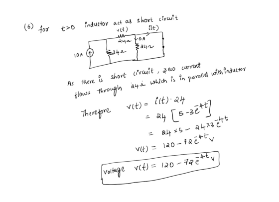
Problem 6) The inductor current in the circuit shown below is given by i(t)=5–3e * A...
The inductor current in the circuit shown in Figure is given by i(t)-5 + 11 e-4tA...
 The inductor current in the circuit shown in Figure is given by i(t)-5 + 11 e-4tA for t 2 0 Determine v(t) for t > O. 84 Ω 14H 84 Ω D10 A 84 Ω e-4t y for t20 2 Answer: v(t) -
Problem 1. For the circuit below, given a value foris 2.5Au(-t) solve for R1 so that...
 Problem 1. For the circuit below, given a value foris 2.5Au(-t) solve for R1 so that the initial capacitor voltage v(0) İs-10V Ri 20 mH 5Ω Problem 2. Circle one: The type of response for v() for t>0 would be classified as Over Damped Critically Damped Under Damped Problem 3. What is the form of the solution for v() for t>0 (form of solution Table 9.1)? Problem 4. What is the initial inductor current iL(0) in Amperes? iL(0)- Problem 5....
1) For the circuit below, a) Find i(t) fort > 0 b) Find vu(t) fort >...
 1) For the circuit below, a) Find i(t) fort > 0 b) Find vu(t) fort > 0 [you can do this by using your answer to part a) and the relationship between voltage across an inductor and current through an inductor] c) Plot your answers to parts a) and b) on separate plots. I lists to V. (4) 2H 2) For the circuit below, if the capacitor is fully discharged for t < 0, a) Find i(t) fort 0 you...
Problem 5: Consider the circuit shown in the figure below in which the initial inductor current...
 Problem 5: Consider the circuit shown in the figure below in which the initial inductor current and capacitor voltage are both zero. (a) Write the differential equation for vc(t). (b) Find the particular solution. (c) Is this circuit overdamped, critically damped, or underdamped? 4 0 i(t) vc()
Problem 2: For the circuit shown below, find the following: The expression of i(t) fort >...
 Problem 2: For the circuit shown below, find the following: The expression of i(t) fort > 0. The voltage vc (t) fort > 0 Calculate the peak energy stored in the capacitor Calculate the real power dissipated in the load formed by R and C. b) d) 40 UF + 0 -V-24 Ve0 400 Hz
Problem 8 In the given circuit i(0) = 3A Determine: a) i(t) (5 points) and b)...
 Problem 8 In the given circuit i(0) = 3A Determine: a) i(t) (5 points) and b) vo(t) (5 points) for t > 0 cos(5t) A 0 3h 5 *,
Problem: The current in and the voltage across a 5 Hinductor are known to be zero...
 Problem:
The current in and the voltage across a 5 Hinductor are known to be zero fort <= 0. The voltage across the inductor is given by the graph in fort >= 0. A. Write the expressions that describe the current i(t) in piece-wise linear representation in suitable intervals. Find the current in the inductor at t2 s. B. Derive the expressions for the inductor power and energy. Use the passive sign convention. Sketch the current, power and energy waveform...
Problem:
The current in and the voltage across a 5 Hinductor are known to be zero fort <= 0. The voltage across the inductor is given by the graph in fort >= 0. A. Write the expressions that describe the current i(t) in piece-wise linear representation in suitable intervals. Find the current in the inductor at t2 s. B. Derive the expressions for the inductor power and energy. Use the passive sign convention. Sketch the current, power and energy waveform...
5. For the circuit shown below, find the current iu(t) flowing in the 4 H inductor...
 5. For the circuit shown below, find the current iu(t) flowing in the 4 H inductor fort20. 4Ω i, (t) t=0 4 H 12 V 50 mF 8Ω
Problem 5(15 pts) The shown circuit is in DC steady state at t <0. The switch...
 Problem 5(15 pts) The shown circuit is in DC steady state at t <0. The switch moves from left to ri t-0. Find i(t) for t 20. 2t 10
The answer is 5 Question 9: In the circuit shown, find the inductor current i(t) for...
 The answer is 5
Question 9: In the circuit shown, find the inductor current i(t) for t20 s (in A) 3Ω 2.5 H İL (t) 20 10 u(t) V 2 S2 (1) 7.5 -2.5 e21 (2) 7.5 -2.5 e0.5t (3) 5 e21 (4) 5 e (5) 6-2 e2t (6) 6-2 e0.5t (7) 4.5 -2.5 e21 (8) 4.5 -2.5 e-0.5t (9) None of the above -0.5t
The answer is 5
Question 9: In the circuit shown, find the inductor current i(t) for t20 s (in A) 3Ω 2.5 H İL (t) 20 10 u(t) V 2 S2 (1) 7.5 -2.5 e21 (2) 7.5 -2.5 e0.5t (3) 5 e21 (4) 5 e (5) 6-2 e2t (6) 6-2 e0.5t (7) 4.5 -2.5 e21 (8) 4.5 -2.5 e-0.5t (9) None of the above -0.5t
 The inductor current in the circuit shown in Figure is given by i(t)-5 + 11 e-4tA for t 2 0 Determine v(t) for t > O. 84 Ω 14H 84 Ω D10 A 84 Ω e-4t y for t20 2 Answer: v(t) -
 Problem 1. For the circuit below, given a value foris 2.5Au(-t) solve for R1 so that the initial capacitor voltage v(0) İs-10V Ri 20 mH 5Ω Problem 2. Circle one: The type of response for v() for t>0 would be classified as Over Damped Critically Damped Under Damped Problem 3. What is the form of the solution for v() for t>0 (form of solution Table 9.1)? Problem 4. What is the initial inductor current iL(0) in Amperes? iL(0)- Problem 5....
 1) For the circuit below, a) Find i(t) fort > 0 b) Find vu(t) fort > 0 [you can do this by using your answer to part a) and the relationship between voltage across an inductor and current through an inductor] c) Plot your answers to parts a) and b) on separate plots. I lists to V. (4) 2H 2) For the circuit below, if the capacitor is fully discharged for t < 0, a) Find i(t) fort 0 you...
 Problem 5: Consider the circuit shown in the figure below in which the initial inductor current and capacitor voltage are both zero. (a) Write the differential equation for vc(t). (b) Find the particular solution. (c) Is this circuit overdamped, critically damped, or underdamped? 4 0 i(t) vc()
 Problem 2: For the circuit shown below, find the following: The expression of i(t) fort > 0. The voltage vc (t) fort > 0 Calculate the peak energy stored in the capacitor Calculate the real power dissipated in the load formed by R and C. b) d) 40 UF + 0 -V-24 Ve0 400 Hz
 Problem 8 In the given circuit i(0) = 3A Determine: a) i(t) (5 points) and b) vo(t) (5 points) for t > 0 cos(5t) A 0 3h 5 *,
 Problem:
The current in and the voltage across a 5 Hinductor are known to be zero fort <= 0. The voltage across the inductor is given by the graph in fort >= 0. A. Write the expressions that describe the current i(t) in piece-wise linear representation in suitable intervals. Find the current in the inductor at t2 s. B. Derive the expressions for the inductor power and energy. Use the passive sign convention. Sketch the current, power and energy waveform...
Problem:
The current in and the voltage across a 5 Hinductor are known to be zero fort <= 0. The voltage across the inductor is given by the graph in fort >= 0. A. Write the expressions that describe the current i(t) in piece-wise linear representation in suitable intervals. Find the current in the inductor at t2 s. B. Derive the expressions for the inductor power and energy. Use the passive sign convention. Sketch the current, power and energy waveform...
 5. For the circuit shown below, find the current iu(t) flowing in the 4 H inductor fort20. 4Ω i, (t) t=0 4 H 12 V 50 mF 8Ω
 Problem 5(15 pts) The shown circuit is in DC steady state at t <0. The switch moves from left to ri t-0. Find i(t) for t 20. 2t 10
 The answer is 5
Question 9: In the circuit shown, find the inductor current i(t) for t20 s (in A) 3Ω 2.5 H İL (t) 20 10 u(t) V 2 S2 (1) 7.5 -2.5 e21 (2) 7.5 -2.5 e0.5t (3) 5 e21 (4) 5 e (5) 6-2 e2t (6) 6-2 e0.5t (7) 4.5 -2.5 e21 (8) 4.5 -2.5 e-0.5t (9) None of the above -0.5t
The answer is 5
Question 9: In the circuit shown, find the inductor current i(t) for t20 s (in A) 3Ω 2.5 H İL (t) 20 10 u(t) V 2 S2 (1) 7.5 -2.5 e21 (2) 7.5 -2.5 e0.5t (3) 5 e21 (4) 5 e (5) 6-2 e2t (6) 6-2 e0.5t (7) 4.5 -2.5 e21 (8) 4.5 -2.5 e-0.5t (9) None of the above -0.5t
Most questions answered within 3 hours.
-
A hot-air balloon is descending with a velocity of (−2.00m/s)y^.
A champagne bottle is opened to...
asked 16 minutes ago -
1. When a nearsighted person looks at an object that is in the
distance with their...
asked 1 hour ago -
QUESTION 8
Both of these statements will store the same value in the
variable $number
$number...
asked 1 hour ago -
The price of 1 lb of potatoes is $1.75. If all the potatoes sold
today at...
asked 2 hours ago -
Garcia Company issues 20.00%, 15-year bonds with a par value of
$470,000 and semiannual interest payments....
asked 2 hours ago -
In C++ Programming, Try using loops only.
This lab demonstrates the use of the While Loop...
asked 3 hours ago -
Effect of DCMU and sodium azide on Chlamydomonas? We did an
experiment where we had Chlamydomonas...
asked 4 hours ago -
1a) According to the ideal gas law, _______________.
a. a gas has infinite volume at absolute...
asked 5 hours ago -
Oakdale Fashions, Inc. had $245,000 in 2018 taxable income.
Using the tax schedule in Table 2.3...
asked 6 hours ago -
The marketing class at CSUS had an average score of 150. An
educational analyst determined that...
asked 7 hours ago -
Justin Case has purchased a $250 000 home by putting 20 % down
and taking out...
asked 7 hours ago -
1. In a labor market, marginal cost for a firm is
____________.
a. recruiting cost
b....
asked 8 hours ago